


Thermal Drift in Gantry Machining Centers During Long Cutting Cycles
Thermal Drift in Gantry Machining Centers During Long Cutting Cycles
Thermal drift can quietly undermine accuracy in a gantry machining center during extended cutting cycles. A machine may produce acceptable dimensions after warm-up, yet leave a depth error or mismatch between surfaces hours later. Heat changes the relationship between the tool tip and the workpiece, even when the CNC reports that every axis has reached its commanded position.
For technical evaluation, the useful question is not simply whether the machine has thermal compensation. It is whether its thermal behavior remains predictable through the intended production cycle—including heavy roughing, finishing, tool changes, pauses, and overnight operation.
Why a stable spindle reading does not mean a stable machine
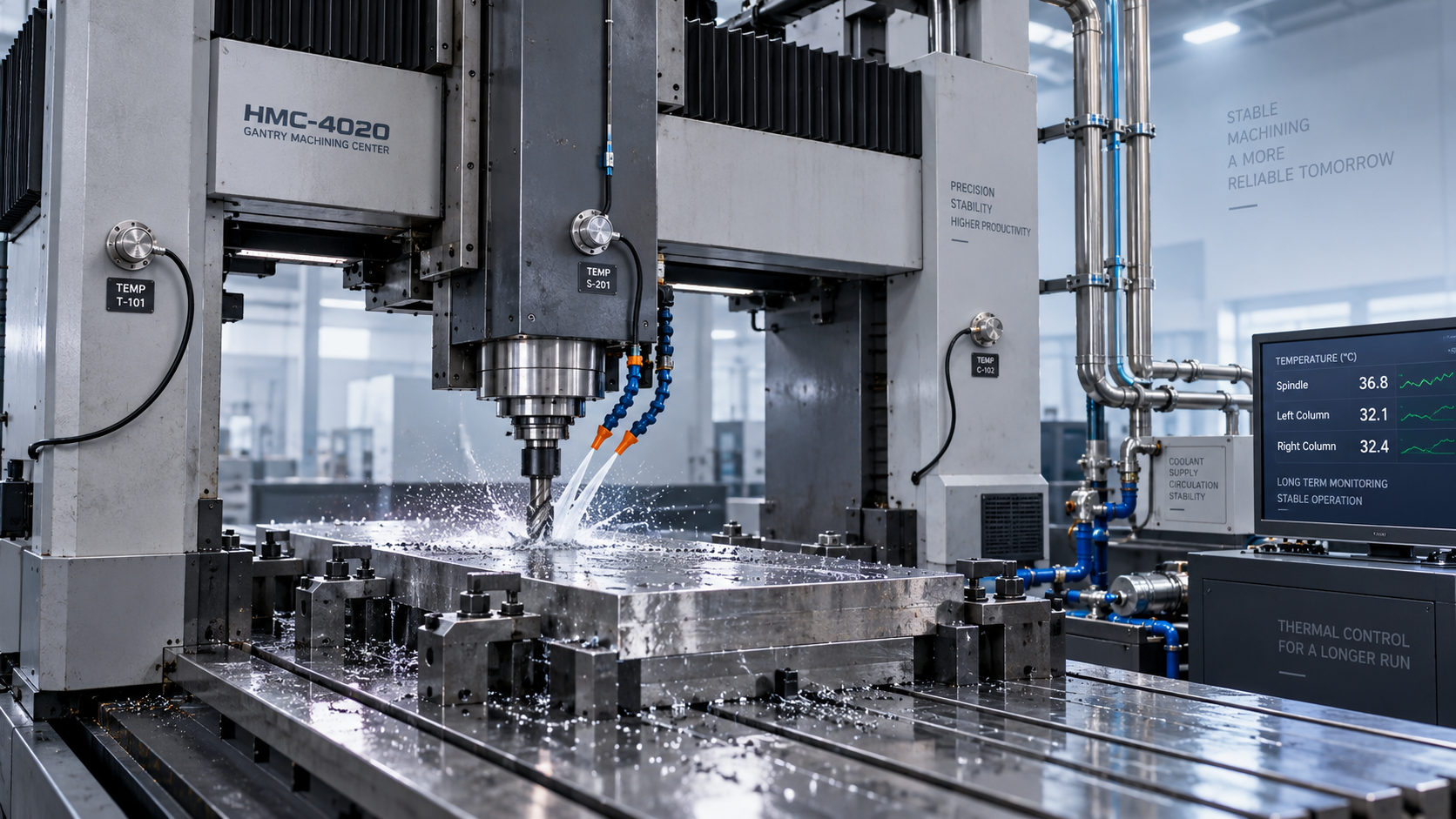
Several heat sources act on different time scales. Spindle bearings and the drive system generate heat during rotation. Axis motors, ballscrews where fitted, and guideway friction add heat during movement. Cutting transfers energy into chips, coolant, the tool, and the workpiece. Meanwhile, room temperature and nearby equipment influence the machine structure from outside.
The difficulty is uneven heating. Uniform expansion is comparatively straightforward to model; temperature gradients can bend or tilt components. On a large gantry, unequal heating of the columns or crossrail may change tool orientation as well as position. A temperature sensor near the spindle cannot describe that entire condition.
Travel also matters. A short, repetitive toolpath concentrates axis activity differently from a program that repeatedly crosses the full working envelope. Consequently, a warm-up routine that stabilizes one production job may not prepare the machine adequately for another.
As a scale illustration—not a machine accuracy prediction—a one-meter steel component undergoing a uniform 5°C temperature increase would expand by roughly 60 micrometers, using a typical expansion coefficient of approximately 12 micrometers per meter per degree Celsius. Actual tool-to-workpiece error depends on geometry, material, constraints, and which components heat together.
Read the error pattern before changing offsets
Consider a large plate that is rough-machined, pocketed, and then finish-faced during one extended setup. The final pass occurs under a different thermal condition from the first operation. If a critical shoulder was finished early, its relationship to the final face may differ from the programmed geometry, even though each individual pass looked consistent.
A gradual shift across successive features can indicate time-dependent drift. An error that changes with crossrail position may suggest structural deformation or position-dependent behavior. A sudden change after a spindle-speed transition deserves investigation of the spindle’s thermal response. None of these patterns proves a cause, but each helps narrow the test.
Do not overlook the part itself. A workpiece measured warm in the fixture may change size after cooling and unclamping. Likewise, on-machine probing does not automatically provide an independent reference: the probe uses the same machine structure and coordinate system. It can support process control without necessarily revealing every source of error.
Make the acceptance test resemble the actual shift
A brief positioning demonstration cannot establish long-cycle thermal capability. ISO 230-3 addresses determination of thermal effects on machine tools and provides a useful framework for discussing test methods. However, citing the standard is not enough; the agreed conditions, measurement arrangement, and reported results determine whether the evidence is relevant.
Before testing, agree on the operating envelope and the permissible error at the features that matter. A practical evaluation should capture:
- Initial machine condition, ambient temperature, coolant temperature, and the warm-up sequence.
- Spindle speeds, loads, axis travel, tool changes, and pauses representative of the intended job.
- Tool-to-workpiece displacement at agreed locations, alongside relevant temperature measurements.
- Compensation status, any manual offset changes, and the measurement system’s uncertainty.
- Behavior after interruption and restart, not just during uninterrupted running.
Duration should follow the process being assessed rather than an arbitrary demonstration window. Some thermal effects develop slowly, and apparent stability at one location may hide continued movement elsewhere. Where practical, use independent displacement measurements and a representative machining trial, then inspect the part under agreed temperature conditions.
Repeatability across separate runs matters as much as the best result. A smooth drift curve that repeats may be manageable. A smaller but inconsistent shift can be harder to control because yesterday’s correction may not work today.
Control heat before asking compensation to correct it
Start with thermal consistency. Maintain cooling circuits, keep heat exchangers clean, and check coolant delivery under cutting conditions. Avoid direct drafts or sunlight on one side of the machine. A tightly controlled spindle chiller does not eliminate errors caused by an unstable room or a progressively warming coolant tank.
Warm-up should reproduce meaningful spindle and axis activity, not merely consume a fixed number of minutes. After a long stoppage, use a defined restart check before finishing critical features. Repeatedly adjusting offsets without logging temperature and operating history can hide the underlying behavior and create errors when the machine cools.
Thermal compensation is valuable when its inputs and model represent actual operating conditions. Ask which heat sources it covers, whether its response varies with axis position, and how it behaves outside the calibration conditions. Compensation for spindle growth alone should not be presented as correction for all structural and workpiece effects.
Process planning offers another lever. Leave suitable finishing allowance after roughing, allow thermal recovery where justified, and machine tightly related features under comparable conditions. There is a trade-off: an extra dwell may protect geometry but extend the cycle. The decision should follow measured drift and tolerance requirements, not habit.
Keep secondary operations in the right category
Not every hole on a large fabrication needs gantry finishing. Noncritical secondary drilling may sometimes be separated from the precision cycle. The VDG60, for example, is a magnetic drill specified with a 50 mm maximum drilling diameter, 1500 W power, and 12000 N magnetic base suction force—not a gantry machining center. Its suitability depends on material, contact condition, cutter requirements, and safe mounting. It should not be treated as an equivalent process for precision positional features.
What to request from the machine supplier
For a supplier such as Shandong VEDON Intelligent Equipment Co., Ltd., whose business spans CNC machine tools, intelligent manufacturing solutions, precision cutting tools, and service, the useful discussion connects machine design with the proposed cutting process. Request the relevant thermal test records, cooling-system requirements, compensation scope, and recommended recovery procedure after downtime.
Keep those conditions in the acceptance agreement. The decisive evidence is not a single cold-machine accuracy figure, but whether the gantry machining center maintains the required feature relationships through the production cycle you intend to run.

Vedon
Typically replies within minutes
Any questions related to Home?

Elaine / Sales Director

Jaye / Sales Manager

Jessica / Sales Manager