


Choose a Horizontal Milling Machine by its ability to sustain your required cut at working speed, with stable dimensions, predictable tool life, and manageable downtime.
Spindle power and table size provide starting points. Technical evaluators also need continuous torque data, structural details, spindle interface specifications, and evidence from representative machining trials.
The strongest candidate matches your steel grades, workpiece dimensions, tolerances, and production targets. A larger motor alone cannot compensate for weak workholding or unstable cutting conditions.
Use the following criteria to build a purchasing specification, compare supplier claims, and establish acceptance tests that reveal whether the proposed configuration suits your actual production.
Start With the Steel, Workpiece, and Required Cut
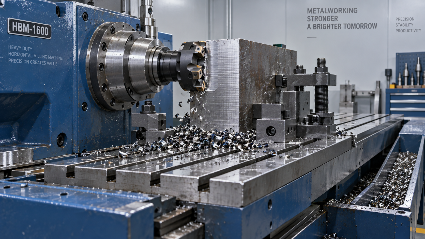
Before comparing machines, define the material grade, hardness range, stock condition, and machining allowance. These factors influence cutting forces, insert selection, heat generation, and achievable productivity.
Include your largest and least rigid components. A compact steel block and a long weldment may require different fixture arrangements despite fitting the same table.
Specify the intended operations: face milling, shoulder milling, slotting, boring, or interrupted roughing. Each places different demands on spindle loading, axis thrust, and chip clearance.
Record cutter diameter, effective tooth count, cutting speed, feed per tooth, axial depth, and radial engagement. Without these inputs, supplier productivity comparisons have limited meaning.
Also distinguish conventional horizontal mills from CNC horizontal machining centers. Arbor support, pallet systems, indexing arrangements, and automation options should follow your actual machining requirements.
Will the Spindle Deliver Enough Torque at Your Cutting Speed?
Heavy steel roughing often requires substantial torque at relatively low spindle speeds. Maximum motor power may occur well above the speed used by your cutter.
Request the spindle torque and power curves, identifying continuous ratings, intermittent ratings, permissible operating durations, and cooling conditions. Peak figures alone cannot demonstrate sustained roughing capacity.
For a stated operating point, torque in newton meters equals 9,550 multiplied by power in kilowatts, divided by spindle speed in revolutions per minute.
For example, delivering 15 kilowatts at 300 rpm requires approximately 478 newton meters. Check whether the spindle continuously delivers that combination within its published operating envelope.
A gearbox can increase available spindle torque at lower speeds. Compare its ranges, transmission losses, shifting requirements, and maintenance needs against the proposed direct drive configuration.
Check available axis thrust and feed capability under cutting load as well. Adequate spindle torque offers little benefit if feed axes cannot sustain the programmed cut.
How Can You Judge Rigidity Beyond Machine Weight?
Machine mass provides context, but it does not establish stiffness at the cutting point. Examine the complete force path through the spindle, structure, fixture, and workpiece.
Ask suppliers about column geometry, guideway arrangement, spindle bearing support, and table support at travel extremes. These details help explain performance differences between similarly sized machines.
Check the proposed spindle interface against cutter diameter, overhang, and expected bending loads. Taper size, contact arrangement, retention force, and toolholder condition all influence cutting stability.
For arbor mounted cutters, evaluate arbor diameter, unsupported length, and outboard support. For machining centers, minimize toolholder extensions and verify clearance before accepting the tooling package.
Request machining evidence at realistic tool reach and workpiece positions. A short cutter working near the machine center may conceal weaknesses affecting your actual components.
Evaluate foundation requirements before purchase. Floor capacity, anchoring, leveling, and installation conditions can influence stability, especially when heavy fixtures and changing pallet loads are involved.
Check Workholding, Chip Removal, and Thermal Behavior Together
Confirm usable working space with the fixture, cutter, spindle nose, and rotary table included. Nominal travels do not guarantee access to every required machining surface.
Verify table or pallet load limits against the combined component and fixture mass. Ask whether load distribution, center of gravity, or indexing introduces additional restrictions.
On indexed machines, examine rotary clamping capacity and allowable machining moments. Positioning accuracy alone does not establish resistance to the forces generated during heavy roughing.
Horizontal spindle orientation can help chips fall away from the cut, but pockets, fixtures, and enclosure ledges may still collect chips and cause repeated cutting.
Inspect conveyor capacity, filtration, coolant delivery, and maintenance access. Match coolant pressure and flow to the selected tools, including through spindle delivery where the application requires it.
Assess dimensional behavior through warmup, sustained roughing, and finishing. Temperature control and compensation need validation under the duty cycle your production schedule will actually impose.
Make the Acceptance Trial Prove Production Capability
Agree on the trial conditions before placing an order. Use representative steel, documented hardness, realistic tooling, production style workholding, and agreed measurement methods for the demonstration.
Require sufficient cutting time to expose thermal drift, chip accumulation, and tool wear. A brief demonstration may show immediate capability without proving sustainable production performance.
For milling, estimate material removal rate from axial depth multiplied by radial engagement and table feed. Use consistent units when comparing different proposed cutting strategies.
Interpret spindle load readings alongside the machine's rating definitions and operating range. Displayed percentages are useful trends, but they are not universally comparable torque measurements.
Set numerical acceptance limits for cycle time, critical dimensions, surface finish, and tool consumption. Document inspection temperature, instruments, sampling frequency, and responsibility for resolving failed results.
Separate Milling Requirements From Supporting Drilling Tasks
Some fabrication workflows also need portable holemaking on large steel structures. Evaluate that requirement separately so auxiliary equipment specifications do not distort the milling machine decision.
For industrial metal drilling applications, the VDG60 magnetic drill is listed with a 50 mm maximum drilling diameter, 1500 W rated power, and 12000 N magnetic holding force.
Its listed no load speed is 0–600 rpm. Confirm diameter capability for the intended cutter and steel, plus holding requirements for actual surface thickness and condition.
This drilling equipment supports a different operation from horizontal milling. Its specifications do not establish milling capacity, and magnetic holding force depends on installation conditions.
Choose the Machine With the Strongest Verified Production Case
Compare total cost using accepted cycle times, tool consumption, staffing, energy, maintenance, and expected availability. Include fixtures, tooling, coolant equipment, installation, and training in the investment.
Ask Shandong VEDON Intelligent Equipment Co., Ltd. for configuration specific documentation, service arrangements, spare parts availability, and application support relevant to the proposed CNC machine tool.
Select the Horizontal Milling Machine that demonstrates stable cutting on your steel, meets dimensional requirements throughout the cycle, and supports an economically sustainable production rate.
Make documented trial results and measurable acceptance criteria part of the purchase agreement. They provide a firmer decision basis than headline power, machine weight, or unsupported productivity claims.