


Horizontal Milling Machine Arbor Supports: Why Rigidity Matters
Horizontal Milling Machine Arbor Supports: Why Rigidity Matters
A horizontal milling machine can have ample spindle power and still struggle with a wide slab cutter. The limiting factor may be the arbor assembly rather than the motor. Under load, small movements at the arbor, support bearing, or overarm can change the cutter’s position relative to the workpiece. The result may be chatter, dimensional variation, uneven surface finish, or premature cutting-edge failure.
Arbor support rigidity therefore deserves more attention than a catalogue photograph can provide. The useful question is not simply whether a machine includes an outboard support, but whether the complete assembly remains stable under the intended cutting conditions.
Follow the cutting force through the assembly
On a conventional arbor-type horizontal mill, the spindle drives an arbor carrying one or more cutters. An outboard support, usually mounted on an overarm, supports the arbor journal away from the spindle. This arrangement limits bending compared with an otherwise equivalent unsupported overhang. It does not eliminate deflection.
Cutting forces pass through the cutter, arbor, spindle bearings, support bearing, overarm, and machine structure. Compliance at any connection contributes to relative movement between tool and workpiece. A heavy support casting cannot compensate for a loose overarm clamp, worn bearing, damaged locating surface, or flexible workholding.
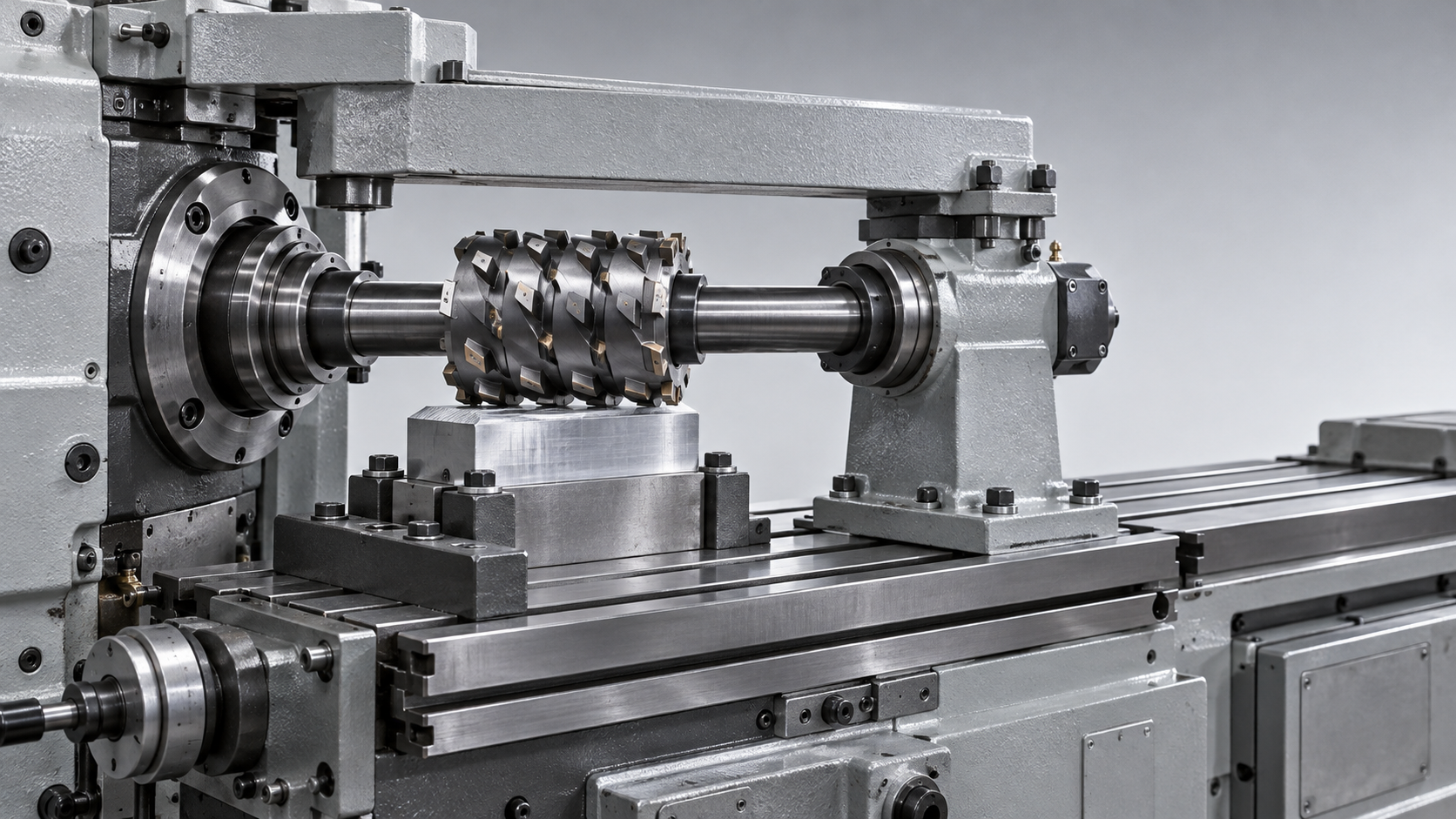
Also check which machine architecture is being discussed. Many horizontal machining centers use spindle-mounted toolholders without an external arbor support. Their rigidity assessment differs from that of a long-arbor machine used for slab, side-and-face, or gang milling. The two should not share an acceptance checklist without adjustment.
Why diameter, span, and cutter position matter
Basic beam mechanics explain why apparently small setup changes can matter. For a solid circular section, bending stiffness depends on the area moment of inertia, which scales with the fourth power of diameter. Deflection also rises strongly with unsupported length. Exact behavior depends on load position and boundary conditions, so a simple beam calculation is a screening tool—not a prediction of complete machine performance.
In practice, use the shortest suitable arbor and the largest diameter compatible with the spindle, cutters, and support. Keep the support close to the cutting zone where clearance permits. Avoid unnecessary spacer length, and evaluate cutter placement relative to both support points rather than treating every position along the arbor as equally rigid.
Gang milling makes these choices more demanding. Several cutters can generate combined forces and moments across a longer assembly. A setup that performs acceptably with one narrow cutter does not establish suitability for a wide cutter stack. The proposed production arrangement should be part of the evaluation.
Static stiffness does not tell the whole story
A static load test measures displacement under an applied force. Chatter is a dynamic problem involving structural modes, damping, cutting conditions, and the interaction between successive tooth passes. A support may show little static movement yet still permit vibration at particular spindle speeds.
More rigidity generally helps, but “chatter-free” should never be accepted as an unconditional specification. Cutter geometry, tooth engagement, runout, workholding, and material all affect stability. Changing speed may suppress one unstable condition without correcting the underlying mechanical weakness.
Inspect interfaces, not just casting size
The support bearing must suit the arbor journal and the machine’s operating range. Depending on the design, it may use a plain bearing or a rolling-element arrangement. Clearance, lubrication, alignment, and permissible speed require design-specific instructions; there is no universal adjustment value.
Too much clearance can allow movement. Excessive tightening or misalignment can cause heating, binding, and accelerated wear. Forcing a misaligned support into position may bend the arbor before cutting begins. Inspect seating surfaces and follow the manufacturer’s alignment and clamping sequence rather than using clamp force to overcome an assembly problem.
- Check arbor and spindle runout separately to help locate the source of error.
- Inspect spacers, cutter faces, and locating shoulders for burrs, contamination, and damage.
- Verify that the overarm locks securely at the required extension.
- Confirm bearing lubrication requirements, replacement parts, and inspection access.
Ease of repeatable setup matters in production. If correct alignment is difficult to verify after each cutter change, performance may depend too heavily on operator technique.
Turn rigidity claims into an acceptance test
Ask suppliers to define the configuration behind their performance claims: arbor diameter, support position, cutter dimensions, material, speed, feed, depth of cut, and workholding. Without these details, a surface-finish sample or cutting video offers limited comparison value.
A useful acceptance plan separates geometric checks from machining tests. ISO 230-1 provides a framework for geometric accuracy testing under no-load or quasi-static conditions, where applicable. It does not by itself establish acceptable chatter behavior in a particular production cut. Specify the applicable test procedures, tolerances, and operating configuration in the purchase documentation.
For the machining trial, use a representative cutter arrangement and workpiece material. Measure dimensions and finish at defined locations, and repeat the cut after the agreed warm-up. Record bearing temperature trends and any abnormal vibration. Acceptance limits should follow the part requirements and machine specification, not an arbitrary universal stiffness number.
If displacement testing is included, document force direction, application point, measurement location, and instrument resolution. A stiffness value expressed as force divided by displacement is meaningful only when those conditions are known.
Keep equipment comparisons technically honest
Rigidity matters across metalworking, but specifications cannot be transferred between unlike machines. For example, the VD16E magnetic drill lists a maximum drilling diameter of 16 mm, a 1,350 W power rating, and nominal magnetic holding force of 11,500 N. That holding-force figure is not a milling arbor stiffness rating; magnetic adhesion also depends on the workpiece and contact conditions. It belongs to a separate drilling-equipment assessment.
Shandong VEDON Intelligent Equipment Co., Ltd. combines R&D, manufacturing, sales, and service across CNC machine tools, intelligent manufacturing solutions, and precision cutting tools. When discussing an application with a supplier covering these categories, keep the milling acceptance criteria distinct from drilling capacity or accessory specifications. Request evidence tied to the actual machine configuration.
For a horizontal milling machine, the decisive evidence is a correctly assembled support system performing the required cut repeatedly. Before approving equipment, settle the arbor arrangement, alignment procedure, production trial, and maintenance requirements. Those details reveal more about usable capability than spindle power or support size alone.

Vedon
Typically replies within minutes
Any questions related to Home?

William / CEO / Brand Founder

Elaine / Sales Manager

Jaye / Sales Director