


What Is a Horizontal Milling Machine Used for in Metalworking?
A horizontal milling machine is used to remove metal from workpieces when machining slots, grooves, flat surfaces, shoulders, and other features that benefit from a horizontally oriented spindle. Common jobs include cutting external keyways in shafts, machining parallel grooves in blocks, and removing substantial stock from castings or forged blanks. Its suitability for a particular job depends on the cutter arrangement, workholding, spindle capability, and access to the required surfaces.
The term covers both conventional machines with arbor-mounted cutters and CNC horizontal machining centers. They share a horizontal spindle orientation, but their tooling and working methods differ. Understanding that distinction makes it easier to connect the machine type with the work it actually performs.
How the horizontal spindle changes the cut
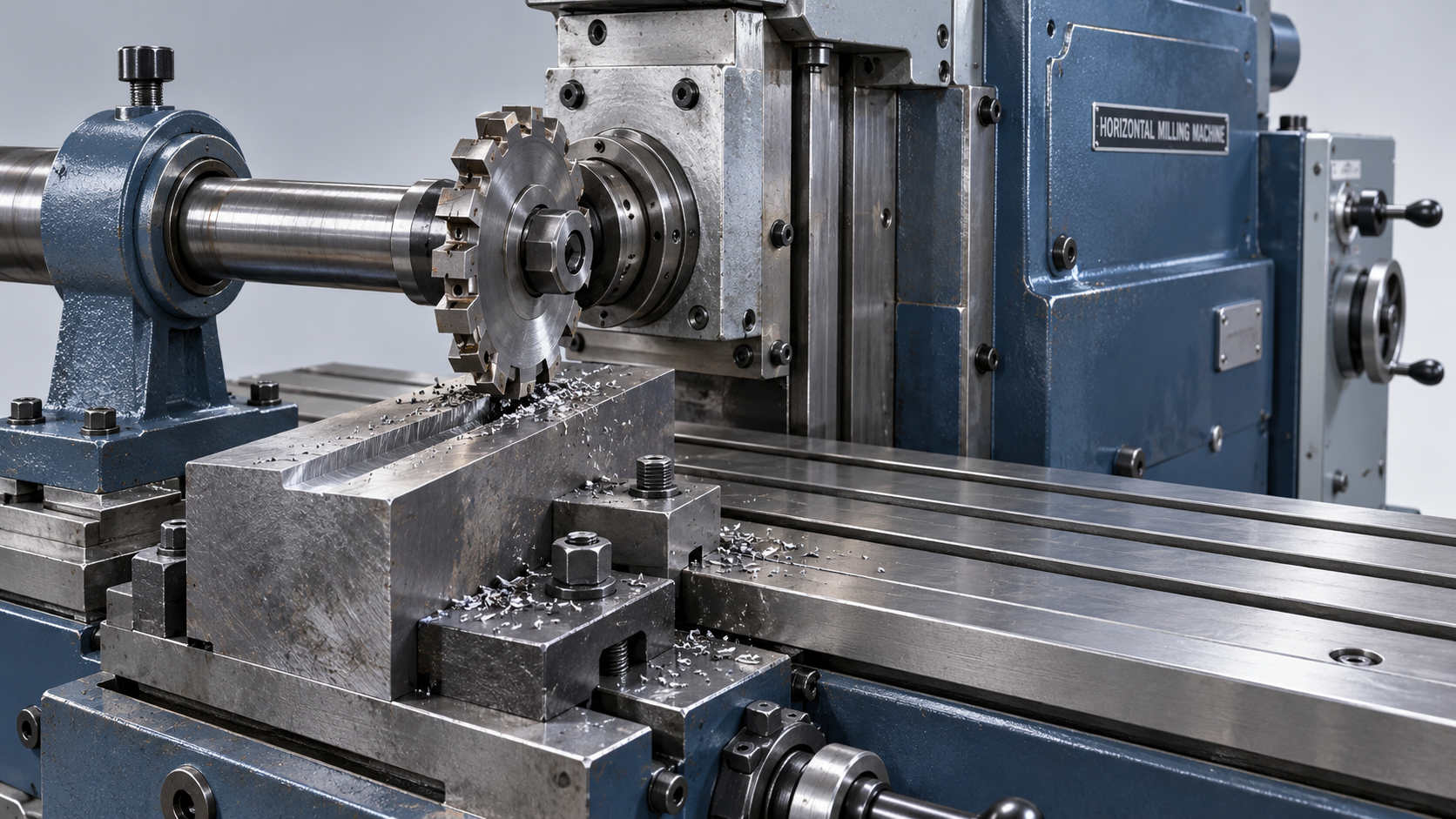
On a conventional horizontal mill, a cylindrical or disc-shaped cutter often mounts on an arbor extending from the spindle. An outboard support helps resist arbor bending. The workpiece moves past the rotating cutter, and teeth around its circumference remove material. This arrangement suits long, straight cuts and operations involving wide cutting engagement.
A CNC horizontal machining center generally holds individual tools directly in the spindle through toolholders. It uses programmed axis movements and frequently incorporates a rotary table or indexing pallet. Face mills, end mills, drills, and boring tools perform different operations without requiring the long arbor associated with a conventional horizontal mill.
Spindle orientation alone does not establish cutting capacity or accuracy. A rigid arbor setup and a compact CNC toolholder arrangement have different limits. Tool overhang, bearing condition, fixture stiffness, and the distance between the cut and its supports all influence how firmly the cutting edge engages the metal.
Slots, grooves, and external keyways
Slotting is one of the clearest applications for a conventional horizontal milling machine. A side-and-face cutter removes material with its peripheral teeth while its side teeth help establish the slot walls. This is useful for channels in machine components, clearance grooves, and slots that extend across an accessible surface.
The slot must suit the cutter’s entry and exit path. A disc cutter naturally leaves a curved termination where its circumference enters or leaves the workpiece. A blind slot requiring a particular end shape may be easier to produce with an end mill, provided tool access and rigidity are adequate.
External keyways in shafts are another common application. The shaft requires secure support against rotation and bending, while cutter alignment establishes the keyway’s position relative to the shaft centerline. An internal keyway inside a bore presents a different access problem and generally calls for broaching, slotting, or another suitable process.
For close-fitting grooves, nominal cutter width is only a starting point. Cutter runout, tooth condition, arbor deflection, and cutting forces affect the finished width. A trial cut followed by measurement helps establish the actual result before the final feature is machined.
Broad surfaces and several features in one pass
Plain milling, also called slab milling, uses a cylindrical cutter to produce a flat surface as the workpiece travels beneath it. It is well suited to accessible surfaces on blocks, plates, and similar components. The cut may remove rough stock or prepare a reference face for subsequent operations.
Straddle milling uses two spaced side cutters to machine opposite parallel faces during the same pass. For example, it can establish two shoulders on a component while controlling their spacing through the cutter and spacer arrangement. The resulting accuracy still depends on cutter runout, spacer condition, and workpiece stability.
Gang milling extends this principle by mounting several cutters on one arbor. Different cutters can produce a combination of flats, grooves, and shoulders as the component passes through the setup. It is useful when a repeated part geometry justifies a dedicated tooling arrangement.
Combining cuts increases the load on the entire setup. A gang of cutters creates greater cutting resistance than a single narrow cutter, so spindle torque, arbor support, feed capability, and fixture strength must match the combined operation. Adding cutters does not automatically shorten production time if the feed must be reduced substantially.
Heavy stock removal and machining housings
Horizontal milling is often associated with heavy cuts because suitable machine structures and supported tooling can resist substantial cutting forces. Roughing operations remove excess material from steel blanks, cast-iron components, and other workpieces before finishing establishes the final dimensions.
Cutting depth alone gives an incomplete picture of the load. Width of engagement, feed per tooth, cutter diameter, material strength, and tool geometry work together. A wide cut at moderate depth can demand more power than a deeper, narrow cut. At low spindle speeds, available torque deserves particular attention; the motor’s headline power rating does not describe every operating condition.
CNC horizontal machining centers are especially useful for housings, valve bodies, and prismatic components with features on several faces. A rotary table can present successive sides to the spindle, allowing face milling, drilling, boring, and contouring within one clamping arrangement. Actual access depends on table travel, indexing capability, fixture clearance, and tool reach.
Keeping a part clamped helps preserve relationships between features on different faces, but rotary-axis accuracy and fixture location still contribute to the result. Deep pockets and recessed bores also require sufficient tool clearance; a horizontal spindle does not eliminate interference between the toolholder, fixture, and workpiece.
Gear teeth and shaped features require the right equipment
A conventional horizontal mill equipped with a dividing head and a suitable form cutter can machine individual gear tooth spaces by indexing the blank between cuts. The cutter must match the intended tooth form and gear geometry. The presence of a horizontal spindle by itself does not make the machine a dedicated gear-production system.
Helical grooves or teeth require coordinated rotation and linear movement, achieved through suitable mechanical arrangements or controlled axes. Likewise, complex three-dimensional surfaces require the necessary axis motion, programming capability, and tool access. A basic manual horizontal mill and a multi-axis machining center should not be treated as interchangeable for these tasks.
When a horizontal layout fits the work
The strongest reasons to select a horizontal arrangement come from the feature geometry and the cutting setup. Long accessible grooves, parallel faces suited to paired cutters, and repeated combinations of features suit conventional arbor milling. Components needing work on several sides often suit a CNC horizontal machining center with an appropriate indexing arrangement.
Chip evacuation is another practical consideration. With the workpiece suitably oriented, chips fall away from vertical faces and some cavities more readily, reducing recutting. Deep pockets can still retain chips, especially when the fixture blocks their exit. Coolant delivery and chip removal must reach the actual cutting zone.
A vertical milling machine often offers more direct visibility and convenient access for shallow pockets, top-face features, and frequent manual setup changes. Neither orientation guarantees a better finish. Chatter marks, tapered walls, and inconsistent dimensions can result from poor support or excessive tool reach on either type.
When reviewing a model listing such as 8835, the model name alone does not establish its suitability for these operations. Relevant specifications include spindle arrangement, usable travel, tooling interface, torque characteristics, table capacity, and any rotary-axis provision. These details connect a machine to the intended cutting operation.
For thin-walled parts, removing material also changes the workpiece’s stiffness during machining. A cut that remains stable near a solid base may chatter as a wall becomes thinner. Leaving finishing stock, supporting vulnerable sections, and choosing a suitable cutting sequence help control that change. The final operation must suit the part’s condition after roughing, when its support and resistance to cutting forces can differ substantially from those of the original blank.

Vedon
Typically replies within minutes
Any questions related to Home?

William / CEO / Brand Founder

Elaine / Sales Manager

Jaye / Sales Director