


Magnetic Drill Motor Stalls Under Load: What to Inspect First
When a magnetic drill stalls under load, stop feeding and release the motor switch immediately. Start with the supply path, cutter condition, and cutting setup before condemning the motor. A drill that runs freely but stops as the teeth engage presents a different fault from one that struggles with the cutter clear of the workpiece.
Before touching the cutter, removing guards, or inspecting the drivetrain, disconnect and isolate the power. Secure the machine independently before doing so: an electromagnetic base loses its holding force when power disappears. Keep the specified safety restraint attached, support the machine against movement, and allow hot tooling to cool. Repeatedly restarting a stalled motor adds heat without identifying the cause.
Use the stopping pattern to choose the first inspection
Record what happened immediately before the stop: cutter diameter, material, selected gear, hole depth, feed behavior, and whether other equipment started on the same circuit. Distinguish an actual stall, where the motor slows toward zero, from an abrupt electrical shutdown. Overload protection, a magnetic adhesion interlock, and an interrupted supply require different follow-up checks.
Measure the supply where the drill receives it
A satisfactory reading at the wall outlet does not establish satisfactory voltage at the machine. Long extension leads, undersized conductors, loose connectors, and damaged plugs introduce resistance. The resulting voltage drop increases as current rises, so the fault often appears only when the cutter enters the material.
With power isolated, inspect the complete cable route for crushed insulation, loose contacts, discoloration, and heat damage. Unwind cable reels as directed by their rating and instructions. Cable suitability depends on conductor size, length, current demand, and the manufacturer's requirements; length alone is insufficient.
Where energized testing is necessary, use a qualified electrical testing procedure and suitable instruments without exposing live conductors. Compare voltage at the drill connection before cutting and during a brief, controlled cutting trial. Stay within the machine's specified supply limits and stop before another stall. A substantial drop that follows increasing load directs attention toward the supply circuit, connectors, or extension lead.
A correctly rated, shorter supply connection is a useful comparison. Change only the supply arrangement during this trial so the result remains interpretable. If a generator supplies the drill, assess its voltage regulation under changing load; its headline power rating alone does not confirm compatibility.
Inspect the cutting edge before increasing feed
With the machine isolated and secured, remove chips using a suitable tool or brush. Inspect the annular cutter for rounded edges, chipped teeth, heat discoloration, and material welded onto the cutting edges. A cutter can look intact from above while its working corners have lost clearance. It then rubs, generates heat, and demands excessive thrust.
Confirm that the cutter suits the material and that its rated cutting depth exceeds the intended hole depth. Diameter affects torque demand, while material hardness and cutter type affect the appropriate cutting speed. Use the cutter supplier's data together with the drill's capacity limits. A speed setting that worked with a smaller cutter is not automatically suitable for a larger one.
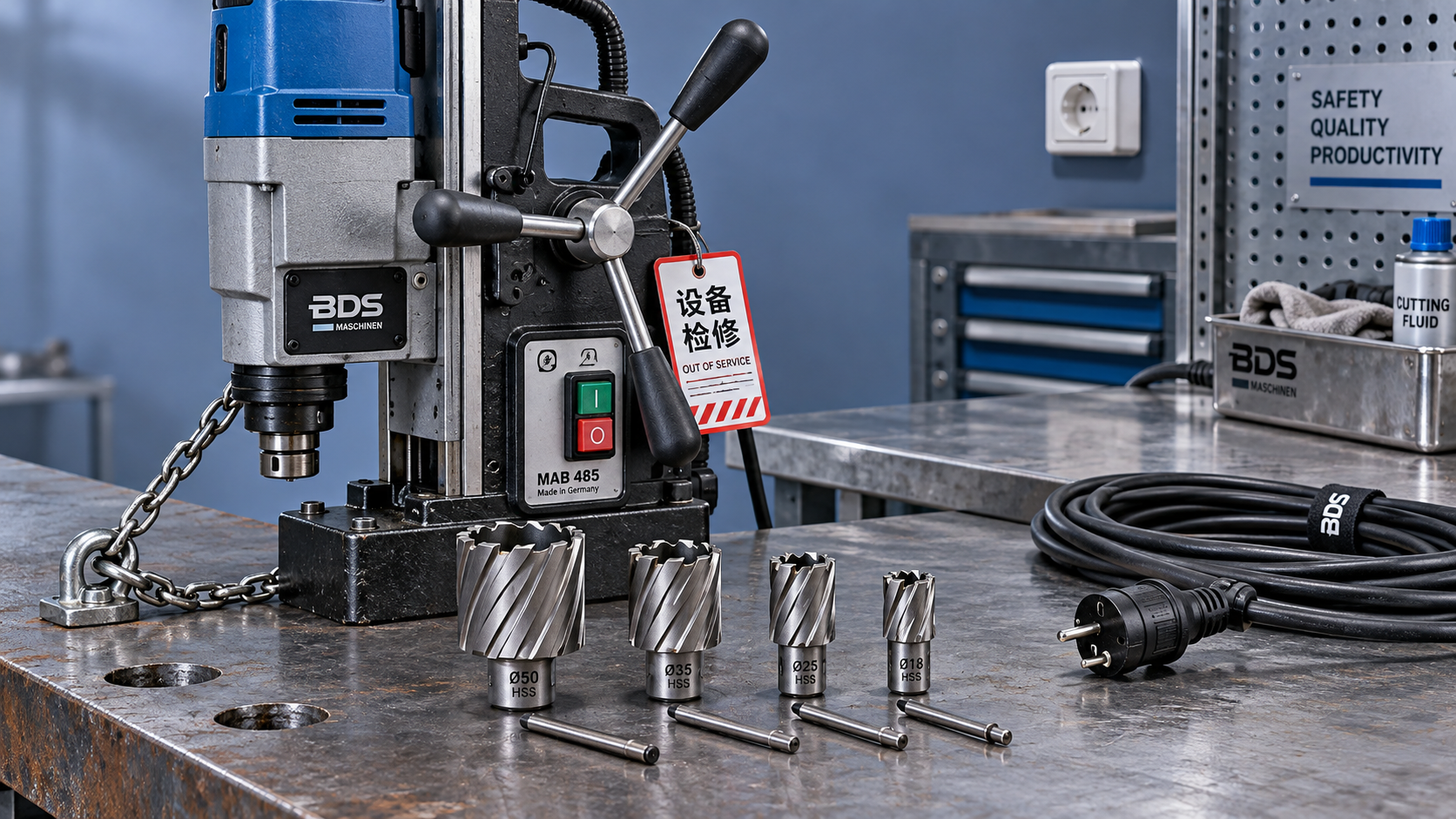
Inspect the arbor seating, retention screws, and pilot pin. A loose or incorrectly seated cutter can run eccentrically and load individual teeth unevenly. Where the pilot operates the coolant valve, verify that it moves as specified and that fluid reaches the cutting zone. Fluid visible outside the hole does not prove that the cutting edges receive adequate lubrication.
Chip behavior helps narrow the diagnosis. Packed chips and increasing resistance with depth suggest poor evacuation. Fine debris, squealing, or polished rubbing marks suggest an edge, speed, or feed problem, although chip appearance varies with material. Do not force a cutter through an obstruction or attempt to clear a rotating tool by hand.
Separate feed overload from movement at the base
During an authorized trial, bring the cutter into contact gradually and establish a stable cut. Excessive feed can pull motor speed down sharply. Insufficient feed can also cause trouble by allowing the edges to rub and heat the surface. Judge feed against sustained cutting, stable speed, and the tooling instructions rather than handle effort alone.
If reducing feed promptly restores speed, investigate cutting demand before opening the motor. Persistent overload at a reasonable feed still requires checks for a dull cutter, unsuitable speed, poor lubrication, or a material change. On machines with mechanical gears, select the specified range with the motor stopped; lowering electronic speed is not necessarily equivalent to selecting a lower gear.
Watch for base rocking, slide movement, and workpiece flex. Paint, scale, chips, curvature, or insufficient steel thickness can reduce magnetic holding performance. Thin plate can deflect under thrust even when the magnet initially feels secure. These movements misalign the cutter and create binding that resembles inadequate motor torque. Follow the machine's requirements for surface condition, thickness, and any approved backing arrangement.
Where loose components can be moved to a fixed machine, the workholding comparison is useful: drilling on a milling machine such as the X6436 uses table-based fixtures rather than magnetic adhesion. That changes how cutting forces are restrained; it does not establish suitable tooling, speed, or capacity for a particular job.
Move inside the machine only when the external checks support it
If the drill still labors clear of the workpiece with a verified supply, isolate power and follow the service manual's mechanical inspection procedure. Look for a partially engaged gear selector, damaged arbor components, bearing roughness, and excessive slide tightness. Do not force the spindle to turn by hand if the drive design prevents back-driving.
Uneven feed travel with the motor disconnected points toward slide adjustment, contamination, or rack damage. Roughness or abnormal noise during an approved unloaded run points toward the rotating assembly. A motor that sounds normal while the spindle stops raises a different question: inspect the transmission or torque-limiting mechanism, if fitted.
Electrical inspection should follow the actual motor design. On a brushed motor, worn brushes, sticking brush holders, or commutator damage can reduce performance; a brushless motor requires a different diagnostic route. Heavy sparking, a burning smell, repeated protection trips, or rapid heating justify stopping operation and proceeding to the specified electrical tests. Never bypass overload protection or magnetic interlocks to continue drilling.
Verify the correction under a controlled cut
After correcting an identified fault, restore guards and secure the workpiece and machine. Run clear of the material first, then make a controlled cut using suitable tooling and the specified settings. Confirm stable speed, effective lubrication, normal chip evacuation, and secure base contact through the relevant cutting depth.
Record the supply arrangement, cutter, material, speed range, and the change that resolved the symptom. If stalling returns only at a particular depth or operating temperature, preserve that detail for the next diagnostic step rather than repeating resets.

Vedon
Typically replies within minutes
Any questions related to Home?

William / CEO / Brand Founder

Elaine / Sales Manager

Jaye / Sales Director