


Why Does a Magnetic Drill Cut Oversized Holes? Alignment Checks
A magnetic drill can cut an oversized hole when the cutter rotates off-center, the machine moves under load, or the cutting teeth remove material unevenly. Replacing the cutter may solve the problem, but first check whether the hole is consistently round and oversized, oval, tapered, or enlarged only at the entry. Those patterns help separate tooling problems from alignment and support problems.
Start by confirming the finished-hole dimensions against the drawing and the cutter manufacturer’s stated capability. A nominal cutter diameter does not guarantee every hole will meet a close dimensional tolerance. If the job requires a precision fit, drilling may need to leave material for a controlled finishing operation.
Read the hole before adjusting the drill
Remove loose chips and burrs before measuring. An entry burr can interfere with the measuring tool and make the opening appear larger than the bore itself. Use an instrument suitable for the specified tolerance; calipers can help identify obvious variation, but closer tolerances may require a bore gauge or another appropriate inspection method.
Measure in more than one direction and, where accessible, at different depths. Also check the hole’s position separately from its diameter. A misplaced hole can still be correctly sized, and moving the drill to correct its location will not resolve oversize cutting.
- Round and consistently oversized: investigate cutter size, tooth condition, mounting, and rotational runout.
- Oval or irregular: check for base movement, workpiece flex, slide play, or chatter.
- Wider at the entrance: look for an unstable start, uneven tooth engagement, or movement before the cutter establishes its path.
- Different dimensions through the thickness: investigate changing support, machine deflection, chip packing, and alignment under load.
These are starting points, not definitive diagnoses. Several faults can produce similar marks. A tilted drill can create an elliptical opening at the plate surface without producing a uniformly oversized bore, so diameter and perpendicularity need separate checks.
Check the magnetic base and workpiece support first
Alignment cannot remain stable if the base shifts or the workpiece bends. Before inspecting the spindle, check the contact between the magnetic base and the steel. Secure the machine against falling or sliding using the restraint specified by its manufacturer, particularly during vertical or overhead work. Stop the spindle and isolate its drive before touching the cutter or adjusting mechanical parts, while maintaining the required magnetic holding and independent restraint.
Inspect the underside of the base and its seating area. Remove chips and address loose scale, uneven coatings, or other contamination that prevents proper contact. Follow the machine’s requirements for surface condition and minimum material thickness. Thin plate, curved surfaces, and incomplete base contact can reduce holding performance.
Check how the workpiece is supported as well. A drill may remain firmly attached while an unsupported plate flexes beneath it. That changes the relationship between the spindle and the cutting surface as feed pressure rises. Support and clamp the work so that cutting loads do not move or bend it.
A model such as the VD68E, with a listed maximum drilling diameter of 68 mm and magnetic holding force of 15,000 N, still depends on suitable contact and workpiece conditions. The holding-force figure alone does not establish how securely the machine will hold on a particular painted, thin, or uneven surface, nor does it establish hole accuracy.
If the base shifts, lifts, or rocks during cutting, stop and correct the setup. Increasing feed pressure to force the cutter through can worsen both movement and hole damage.
Separate spindle alignment from cutter runout
Two checks matter here: whether the spindle axis is correctly oriented to the work, and whether the cutter rotates concentrically around that axis. A drill can be square to the plate while a poorly seated cutter runs off-center. It can also rotate concentrically while leaning relative to the required hole axis.
With the machine safely secured and its drive isolated, inspect the cutter mounting surfaces, shank, arbor, and retaining components. Trapped chips, damaged contact surfaces, an incompatible shank, or incorrect tightening can prevent proper seating. Refit the cutter using the specified mounting procedure and tightening requirements.
Inspect the annular cutter for chipped teeth, uneven wear, built-up material, or damage following a jam. Unequal cutting forces can encourage chatter and deflection. The pilot pin helps locate the cut and, on suitable systems, supports coolant delivery and slug ejection; it does not correct spindle runout or compensate for a moving base.
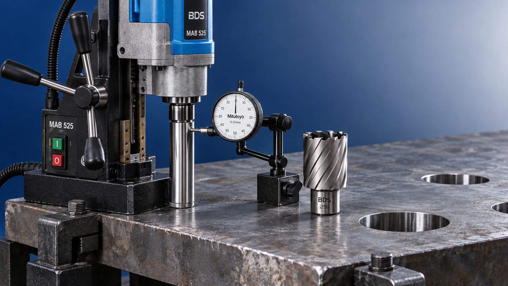
Where the manufacturer permits it, check runout with a dial indicator and a suitable smooth reference surface or test arbor. Rotate the spindle manually according to the service procedure, with power isolated. Avoid using interrupted cutting teeth as an improvised reference: tooth geometry and damage can obscure the reading. Compare results with the machine and tooling manufacturers’ limits rather than adopting an arbitrary universal tolerance.
If excessive runout remains after cleaning and reseating, check progressively from the cutter toward the spindle. A known-good compatible cutter can help isolate a tooling fault. Persistent error at the arbor or spindle may require service for damaged components or bearing wear.
Next, check spindle orientation relative to the intended drilling surface using the manufacturer’s alignment method. Do not assume the motor housing provides an accurate reference. Inspect carriage guides, slide adjustment, and fastening points for looseness. Keep the carriage extension as short as the setup permits; unnecessary extension increases the opportunity for deflection under cutting load.
Check what changes when the cutter starts working
A static alignment check can pass while the hole still becomes oversized under load. Watch for vibration, changing cutting sound, uneven chips, or visible movement from a safe operating position. These signs help identify forces that appear only during cutting.
Set speed and feed for the cutter type, diameter, and workpiece material using the tooling manufacturer’s guidance. A machine’s available speed range is not a cutting recommendation. Excessive feed can deflect the assembly or disturb the base; insufficient feed can cause rubbing and heat. A steady feed that produces effective cutting is more useful than trying to overcome vibration with additional pressure.
At entry, allow the cutter to establish an even cut before applying the normal working feed. Welds, surface curvature, or an angled starting face can make some teeth engage before others, creating an uneven load. If the surface prevents stable engagement, the setup may need a fixture or a different machining approach.
Maintain the specified cutting-fluid supply and chip clearance. Packed chips can increase load, score the wall, and damage teeth. Use a cutter suitable for the material thickness, and follow its procedure for stacked plates or interrupted cuts. Never clear chips by hand while the spindle is rotating. Reduce feed as required near breakthrough, when support beneath the cutting edges changes.
Verify the correction before continuing the batch
After correcting an identified fault, make a controlled trial hole in comparable material with equivalent support. Measure it using the same method as the rejected hole. Record the cutter, setup, speed, and observed defect so that a later change can be traced.
If reseating the cutter restores size, inspect subsequent holes for recurrence. If a known-good cutter still produces oversize holes on a stable, properly supported setup, spindle, arbor, or carriage inspection becomes the next step. Where the required tolerance is tighter than the drilling process can reliably hold, specify a suitable finishing operation before releasing the remaining work.

Vedon
Typically replies within minutes
Any questions related to Home?

William / CEO / Brand Founder

Elaine / Sales Manager

Jaye / Sales Director