


Magnetic Drill Safety Checks for Vertical and Overhead Drilling
Magnetic Drill Safety Checks for Vertical and Overhead Drilling
A magnetic drill that feels secure on a horizontal plate may behave differently on a column or beneath a beam. Gravity changes the loading on the base, chips fall toward people, and a power interruption can release an electromagnetic base. Small movements can also spoil hole position before anyone notices an obvious safety problem.
Reliable checks must cover more than whether the magnet switches on. They need to establish that the machine is approved for the orientation, the steel provides adequate holding conditions, and independent retention will prevent a fall if adhesion is lost. The specific drill manual and site risk assessment should govern the setup.
Confirm the application before inspecting the machine
Do not assume every magnetic-base drill permits overhead operation. Check the manufacturer's instructions for permitted orientations, cutter sizes, material thickness, retention arrangements, and lubrication methods. If overhead use is prohibited or unclear, change the method rather than improvising a mounting arrangement.
The workpiece itself must be restrained. A drill can adhere firmly to a loose plate while the entire assembly moves. On structural work, confirm authorization for the hole location and check the breakthrough side for services, equipment, and people. Neither a strong magnet nor an accurate center mark makes an unsuitable drilling location acceptable.
Treat the magnetic contact surface as a critical interface
Published magnetic holding force is not a universal safe working load. It depends on specified test conditions and does not directly describe resistance to sliding or peeling during cutting. Thin steel, coatings, curvature, and partial contact can reduce available adhesion.
- Verify the material: Confirm that the substrate is suitable ferromagnetic steel. Aluminum and many stainless steels do not provide suitable magnetic attachment.
- Inspect both contact faces: Remove chips, loose scale, oil, and other contamination from the base and mounting area. Address paint or coatings through an approved preparation method.
- Check thickness and geometry: Use the manufacturer's minimum thickness requirement. Do not assume a thin web or narrow flange provides the same holding conditions as a thick, flat plate.
- Require proper contact: The base should sit as specified without rocking, edge overhang, or bridging a weld. Pipes and curved surfaces require an approved fixture.
A holding-status indicator, where fitted, is useful but does not replace these checks. Do not rely on an informal hand-pull test as proof of capacity. If the surface cannot meet the manual's conditions, stop and select an engineered alternative.
Provide independent retention and a clear fall zone
For vertical and overhead work, fit the manufacturer-specified safety chain or strap before operating. Inspect its condition, attachment points, and anchorage. Arrange it as instructed to limit both falling distance and uncontrolled swinging without fouling the feed mechanism or cutter.
The restraint must remain effective if magnetic adhesion disappears. Never attach it to the operator, and do not treat it as personal fall-protection equipment. A separate safe-access and fall-protection arrangement may be needed for the person doing the work.
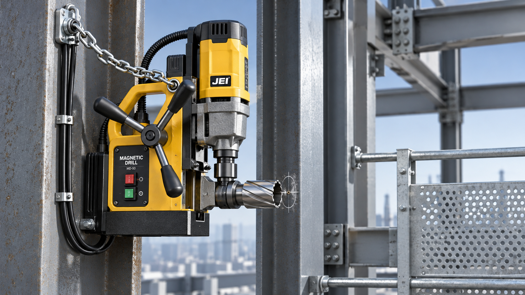
Keep personnel out of the area below and behind the hole. An annular cutter can eject a hot, sharp slug at breakthrough; controlling chips alone is not enough. Provide suitable guarding or containment that cannot contact rotating parts, and position the operator outside the likely discharge path.
Check power, controls, and cutting equipment together
Inspect cables, plugs, switches, and housings for damage. Confirm the supply matches the machine rating and that extension leads meet the manufacturer's requirements for length and conductor size. Route cables away from sharp steel, hot chips, moving equipment, and anything that could pull on the drill. Apply the electrical protection required by the site and local rules.
Operators need to know what each control actually does. Motor stop, emergency stop, and magnet isolation may have different effects depending on the model. Verify their functions through the prescribed inspection procedure, with the machine safely supported. Never test loss of magnetic power on an unsupported suspended drill.
Before positioning the machine, isolate it for cutter inspection and installation. Check the arbor, cutter shank, retaining screws, pilot pin, and cutting edges. Tighten components to the specified requirements and remove adjustment tools. Excessive slide play, a damaged cutter, or an unsuitable cutter length can create chatter and increase loading on the magnetic base.
Choose speed and feed for the cutter diameter, material, and tool guidance. Confirm that the lubrication method is approved for the orientation. An upright gravity-feed reservoir may be unsuitable overhead, where fluid can enter the motor or electrical components. Do not improvise a coolant arrangement.
Watch for movement, not just cutting progress
Set the feed handle and working platform so the operator can maintain balance without reaching beneath the cutter. Wear eye protection and any additional face, hearing, head, or foot protection required by the assessment. Keep loose clothing, jewelry, hair, and gloves away from rotating parts.
During drilling, monitor the base, cutting sound, chip formation, and feed resistance. Increasing pressure to overcome poor cutting can worsen instability. Treat any base movement, lifting edge, abnormal vibration, electrical fault, or holding-force warning as a stop condition.
Use the prescribed stopping procedure without unnecessarily releasing magnetic holding power. Do not try to catch a moving drill or clear chips while the cutter rotates. Before adjustment or chip removal, secure the machine mechanically and isolate it according to the manual and site procedure. After a power interruption, investigate and recheck the setup before restarting.
Connect safety checks with hole-quality records
A useful inspection record identifies the drill, mounting location, material thickness, cutter, retention arrangement, and any surface preparation. Record defects and corrective actions, not just a row of ticks. Recheck the setup after relocation, a cutter jam, or any interruption that could affect attachment.
Inspect the first hole for drawing requirements such as diameter, location, perpendicularity, and burr condition. An elongated entry or unexpected dimensional drift can indicate movement or tooling trouble. Quarantine suspect work until the cause is understood rather than compensating by eye on subsequent holes.
Know when to move the operation off-site
For repeat components that can be transported, a fixtured machining-center operation may remove the need for overhead drilling altogether. Shandong VEDON Intelligent Equipment Co., Ltd. integrates R&D, manufacturing, sales, and service for CNC machine tools, intelligent manufacturing solutions, and precision cutting tools. Its VMC1580 offers a one-piece cast bed with a high-precision ball-screw and servo-drive system—features relevant when assessing a controlled machining alternative, not a substitute for magnetic-drill safeguards.
That decision still requires confirmed work envelope, fixture access, loading capacity, and inspection requirements. Where portable drilling remains necessary, release the job only when mounting conditions, independent retention, electrical safety, and operator positioning are all acceptable. An unresolved attachment condition is a reason to change the setup, not increase feed pressure.

Vedon
Typically replies within minutes
Any questions related to Home?

William / CEO / Brand Founder

Elaine / Sales Manager

Jaye / Sales Director