


Milling Machine Basics: How Table Axes and Feed Direction Shape a Cut
A milling machine can leave a clean surface in one direction and chatter when the pass reverses because reversing the feed changes how the cutting edges engage the material. Chip thickness, cutting-force direction, and the load on the table drive all change. The result also depends on spindle speed, cutter engagement, workholding, and machine stiffness.
Understanding that relationship starts with two separate ideas: the axes describe relative movement between the cutter and workpiece, while conventional and climb milling describe how feed direction relates to cutter rotation at the cut.
Reading X, Y, and Z without confusing table movement
On a typical vertical milling machine, X runs left to right across the table, Y runs front to back, and Z follows the spindle axis. Z movement changes the vertical relationship between the tool and workpiece. Depending on the machine design, that movement comes from the head, quill, knee, or another assembly.
The letters identify coordinate directions, not necessarily which component physically moves. A CNC program describes the tool’s motion relative to the workpiece. If the tool remains stationary along X while the table moves, the table travels opposite to the programmed relative tool motion. Confusing those viewpoints makes feed-direction diagrams difficult to interpret.
These descriptions assume a conventional vertical layout. On a horizontal mill, Z still follows the principal spindle axis, so it is horizontal. Machine documentation establishes positive directions and travel limits; the position of a handwheel alone does not establish the coordinate convention.
Feed direction changes the chip at entry
Each milling tooth enters and leaves the material during rotation. Its chip thickness changes throughout that engagement. For peripheral milling, conventional and climb cutting describe two different relationships between the workpiece feed and the local tangential motion of the cutting edge.
In conventional milling, the workpiece feeds against the cutter’s tangential motion at engagement. The theoretical chip starts at zero thickness and grows toward its maximum before the tooth exits. Near entry, the edge can rub or plough before it forms a chip, particularly with a dull edge or insufficient feed per tooth.
In climb milling, the workpiece feeds in the same direction as that local cutting-edge motion. The tooth enters with the greatest chip thickness for that engagement, and the chip becomes thinner toward exit. On a rigid machine with controlled backlash, this often reduces entry rubbing and supports a better finish.
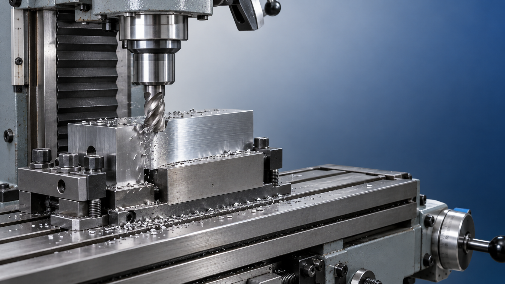
Clockwise spindle rotation alone does not identify the cutting mode. The engaged side of the cutter and the viewing direction also matter. With rotation unchanged, moving from one side of a workpiece to the opposite side changes which feed direction produces climb milling. A useful diagram must show rotation, workpiece feed, and the side in contact.
Full-width slotting adds a complication: opposite sides of the cutter engage under different local relationships. Calling the entire slotting operation “climb milling” hides that distinction. For a finishing pass along one wall, the engaged side is easier to identify and control.
Why backlash changes the choice
Backlash is clearance in the motion system that allows some reversal before the driven component responds. A worn leadscrew and nut provide a familiar example: the handwheel turns briefly after reversal before the table starts moving.
During climb milling, the cutting force tends to draw the workpiece into the cutter along the feed direction. If the table drive has uncontrolled clearance, that force can pull the table through the backlash. The resulting movement increases the tooth load abruptly, risking a damaged edge, a gouged surface, or loss of control.
Conventional milling generally loads the feed mechanism against the commanded workpiece travel, which makes it the more conservative choice on many manual machines with appreciable backlash. Its force components can also tend to lift the workpiece in common peripheral-cutting arrangements, so secure clamping remains necessary.
Many CNC machining centers use preloaded ballscrews and sufficiently stiff feed systems to support climb milling. However, a CNC label alone does not establish suitability. Mechanical wear, bearing condition, fixture stiffness, and the machine’s operating instructions still govern the choice. Software backlash compensation corrects positioning error; it does not remove mechanical clearance or restore stiffness under cutting load.
The same direction can behave differently across a setup
A tall workpiece, long tool extension, or slender end mill bends more readily under load. Reversing the cutting direction changes where the assembly deflects and how the force acts against the fixture. One pass may load the part into a solid support, while the return pass pulls it away from that support.
This explains why reversing a finishing pass can change the measured wall position even when the programmed path is identical. Tool deflection and elastic recovery alter the material actually removed. A light repeat pass sometimes removes additional stock, but repeated passes do not correct a loose fixture or unstable tool assembly.
Axis condition also matters. A worn section of a slideway, an incorrectly adjusted gib, or excessive spindle extension can make vibration worse at a particular table position. Locking an unused axis, where the machine design permits it, can improve stability during a straight manual cut. An axis required for programmed movement must remain free to move.
Workholding specifications also belong to their intended operation. For example, the VDW50 is listed as a magnetic drill for industrial metal drilling, with a maximum drilling diameter of 50 mm. That drilling capacity does not establish suitability for lateral milling loads; machine structure, spindle bearings, tool retention, and the mounting arrangement require separate consideration.
Separating feed problems from other surface defects
Feed direction influences finish, but a rough surface does not prove that the wrong milling mode was selected. Regular feed marks, smeared material, and chatter indicate different mechanisms.
- Regular, evenly spaced marks: Tooth passage and feed per tooth influence their spacing. Cutter geometry and runout affect their depth and consistency.
- Smeared or torn patches: Material adhering to the cutting edge, inadequate lubrication, or rubbing can disrupt chip formation. Simply reducing feed can intensify rubbing.
- Wavy patterns accompanied by vibration: Chatter involves interaction between cutting forces and structural vibration. Tool overhang, engagement, spindle speed, and workholding deserve attention alongside feed direction.
Feed per tooth connects table feed to spindle rotation and tooth count: feed per tooth = feed rate ÷ (spindle speed × number of cutting teeth). Increasing spindle speed while holding feed rate constant reduces the nominal feed per tooth. A setting that sounds faster can therefore produce more rubbing if the edge stops forming an effective chip.
Radial engagement changes actual chip thickness as well. A narrow side cut can produce a thinner maximum chip than the same nominal feed per tooth at greater engagement. This is why a feed value copied from a full-width slot cannot automatically describe the cutting load of a light finishing pass.
Interpreting a pass before changing it
For a straight side-milling pass, first establish the spindle rotation, engaged cutter side, and workpiece movement relative to the tool. Those three observations identify conventional or climb engagement. Then relate the cutting force to the table drive, clamps, and nearest solid support.
A controlled comparison keeps cutter, depth, engagement, and workholding consistent while changing one relevant variable. Where the machine permits both cutting modes, differences in finish or vibration then become meaningful evidence. Record the physical feed direction and engaged side alongside the result; “left to right” alone is ambiguous when the next setup changes orientation.

Vedon
Typically replies within minutes
Any questions related to Home?

Elaine / Sales Director

Jaye / Sales Manager

Jessica / Sales Manager