


Milling Machine Head Tramming: Correcting Steps Between Face Mill Passes
Steps between adjacent face-milling passes are a reason to check head tram, not proof that the head needs adjustment. A spindle tilted relative to the table can leave overlapping cuts at different heights, but insert runout, workpiece movement, axis geometry errors, and cutting deflection can produce similar marks. Adjusting the head before separating these causes can hide one error while introducing another.
The reliable correction is to confirm a measurable height discontinuity, check spindle-to-table alignment under repeatable conditions, and verify the result with a controlled test cut. A surface that looks better after adjustment is not sufficient evidence: both the indicator readings and the machined surface must meet the applicable requirements.
Establish whether the mark is a step or a cutting pattern
Clean the workpiece and inspect the boundary between passes. Changes in cutter engagement can create contrasting light bands without a meaningful height difference. Measure across the boundary with suitable surface-measuring equipment or an indicator setup referenced independently of the suspect surface. Remove burrs without rounding the boundary being measured.
Record the feed direction, lateral stepover, cutter diameter, cutting depth, and whether adjacent passes run in the same or opposite directions. These details help distinguish alignment errors from load-dependent movement.
- A repeatable ridge at each overlap: investigate tram, but also confirm tool seating and insert height.
- A defect that changes substantially with feed direction: check cutting-force effects, backlash where applicable, and fixture rigidity.
- Regular marks within each cutter revolution: inspect insert condition, axial runout, and cutter seating before adjusting machine geometry.
- A height change that grows along the table: investigate table geometry, machine twist, or workpiece support rather than assuming a constant head tilt.
Check the part while clamped and, where the inspection plan permits, after release. A thin workpiece pulled flat by excessive clamping can spring back after machining; head tramming will not correct that distortion.
Remove setup errors before measuring the head
Inspect the spindle taper, holder, cutter mounting faces, and insert pockets for chips, burrs, or damage. Confirm insert seating and tightening against the tooling manufacturer's instructions. Measure cutter axial runout with the assembly installed, using a consistent point on each cutting edge. A single protruding insert can dominate the finish and complicate the diagnosis.
Bring the milling machine to its prescribed thermal condition before precision checks. Record the quill extension, ram position, head position, and axis-lock condition. On a knee mill, use minimal practical quill extension and secure the quill as specified. On other configurations, follow the manufacturer's geometry-check procedure rather than transferring knee-mill practices unchanged.
Remove the cutting tool before installing a sweep indicator. Prevent unintended spindle rotation and machine movement during setup. Use only the controlled axis movements needed for positioning, and rotate the indicator assembly manually under the machine's safe setup procedure. Never power the spindle with a tramming indicator attached.
Sweep a trustworthy reference in both directions
Mount a dial test indicator or suitable tramming instrument rigidly in the spindle. Sweep the table surface, a qualified tramming ring, or a verified reference plate. Clean all contact areas carefully. Avoid slots, dents, and raised edges; an unverified plate can introduce more error than the alignment being checked.
Use the largest practical sweep diameter that remains on a reliable reference and within the instrument's travel. A wider sweep increases sensitivity to angular error. Keep the table stationary while comparing opposite points, maintain consistent stylus geometry, and use light, stable contact pressure.
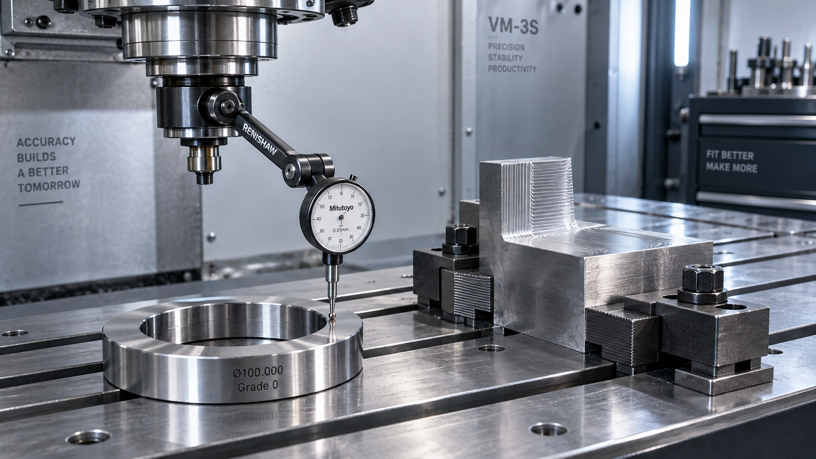
Compare readings at the left and right positions, then at the front and rear positions. These pairs show spindle orientation relative to the reference in two perpendicular planes. Repeat the sweep to establish that the readings are stable. If they do not repeat, investigate indicator mounting, contact conditions, bearing play, or movement in the machine before making an adjustment.
For a small angular error, the approximate relationship is:
Angular error in radians ≈ opposite-point reading difference ÷ sweep diameter.
For example, a 0.02 mm difference across a 200 mm sweep represents approximately 0.0001 radian. This is an illustration, not an acceptance limit. The permitted difference must come from the machine specification, the service procedure, and the accuracy required by the work.
Do not treat the indicator difference as the predicted step between passes. The resulting surface also depends on cutter geometry, stepover, active cutting edges, feed direction, and deflection. The sweep measures alignment; the test cut establishes its effect on machining.
Adjust the head without losing control of the assembly
On an adjustable-head machine, identify the correct swivel or nod adjustment and its associated clamps. Support the head where required by the manufacturer. Loosen fasteners only enough to permit controlled movement; releasing the assembly excessively can allow a heavy head to shift suddenly.
Make a small correction, snug the clamps, and repeat the sweep. With a single indicator, bringing the high and low readings toward their midpoint provides a useful initial target, but the actual response depends on the pivot location and adjustment mechanism. Do not assume a jacking-screw movement produces an equal change at the indicator.
Correct both planes iteratively because tightening or adjusting one plane can affect the other. Tighten fasteners in the specified sequence and to the specified torque, then measure again. A reading obtained with loose clamps is not the final alignment.
For a fixed-head CNC machining center, an unacceptable sweep is not permission to loosen the spindle cartridge or add improvised shims. Check installation condition, machine leveling, crash history, and the manufacturer's alignment procedure. Structural alignment work requires the designated adjustment method and appropriate metrology.
Also distinguish spindle tram from Z-axis motion squareness. A spindle axis can be perpendicular to the table at the measurement position while the head travels along an incorrectly aligned path. Sweeping the table alone does not certify the complete machine geometry.
Prove the correction with a controlled face-milling test
Use a stable test piece with adequate thickness and support. Retain the original cutter and cutting conditions initially, provided they are safe and the tool is serviceable. Changing the tool, feed, workholding, and tram simultaneously makes it difficult to identify which correction solved the defect.
Machine adjacent passes with a documented stepover and consistent Z command. Start with same-direction passes to reduce the influence of reversal-related effects, then reproduce the production toolpath. Measure the height across the overlaps rather than relying on reflected light.
If the sweep meets specification but a step remains, the next action should follow the evidence:
- The step decreases with lower cutting load: investigate tool overhang, head rigidity, workholding, and cutting parameters.
- The defect follows a particular cutter: recheck holder seating, cutter-body condition, insert pockets, and axial runout.
- The error changes with table position: check table condition, axis geometry, installation twist, and support conditions.
- The result changes after warm-up: examine thermal stabilization and spindle growth before repeating mechanical adjustment.
Machine architecture also sets the limits of this procedure. A Y-axis turning center with driven tooling, such as the TCK52DY, requires checks of the driven-tool holder, turret alignment, and relevant axis relationships. A vertical-mill head-tramming procedure should not be applied directly to its BMT tooling arrangement.
Leave a measurable service baseline
Record the sweep diameter, readings in both planes, machine position, thermal condition, final clamp condition, and measured test-cut result. Include cutter identification and machining conditions so a later inspection can reproduce the check.
Close the correction only when the fully secured assembly meets its alignment requirement and adjacent passes meet the workpiece requirement. If the two results disagree, preserve the measurements and investigate the remaining cause rather than repeatedly tilting the head to compensate for an unrelated fault.

Vedon
Typically replies within minutes
Any questions related to Home?

Elaine / Sales Director

Jaye / Sales Manager

Jessica / Sales Manager