Solving Surface Finish Problems on Aluminum Parts Machined by a VMC650
Surface finish defects on aluminum parts can compromise dimensional accuracy, product quality, and shop-floor safety. For quality control and safety managers, identifying the root cause quickly is essential.
This guide explains how to troubleshoot common issues on a VMC650, from tool selection and spindle speed to coolant delivery, machine rigidity, and programming parameters.
When aluminum parts leave a VMC650 with scratches, chatter marks, burrs, tearing, or inconsistent gloss, the problem is rarely caused by one setting alone.
For quality teams, the priority is to separate isolated machining variation from a repeatable process failure before defective parts reach assembly, coating, or customers.
Safety managers should also treat poor finish as a warning sign. Built-up edge, unstable chips, loose fixtures, and damaged tools can create avoidable operator hazards.
A practical investigation begins with the defect pattern. Surface appearance often indicates whether the main cause involves tooling, spindle behavior, workholding, coolant, programming, or material condition.
Start with the Defect Pattern Before Changing VMC650 Settings
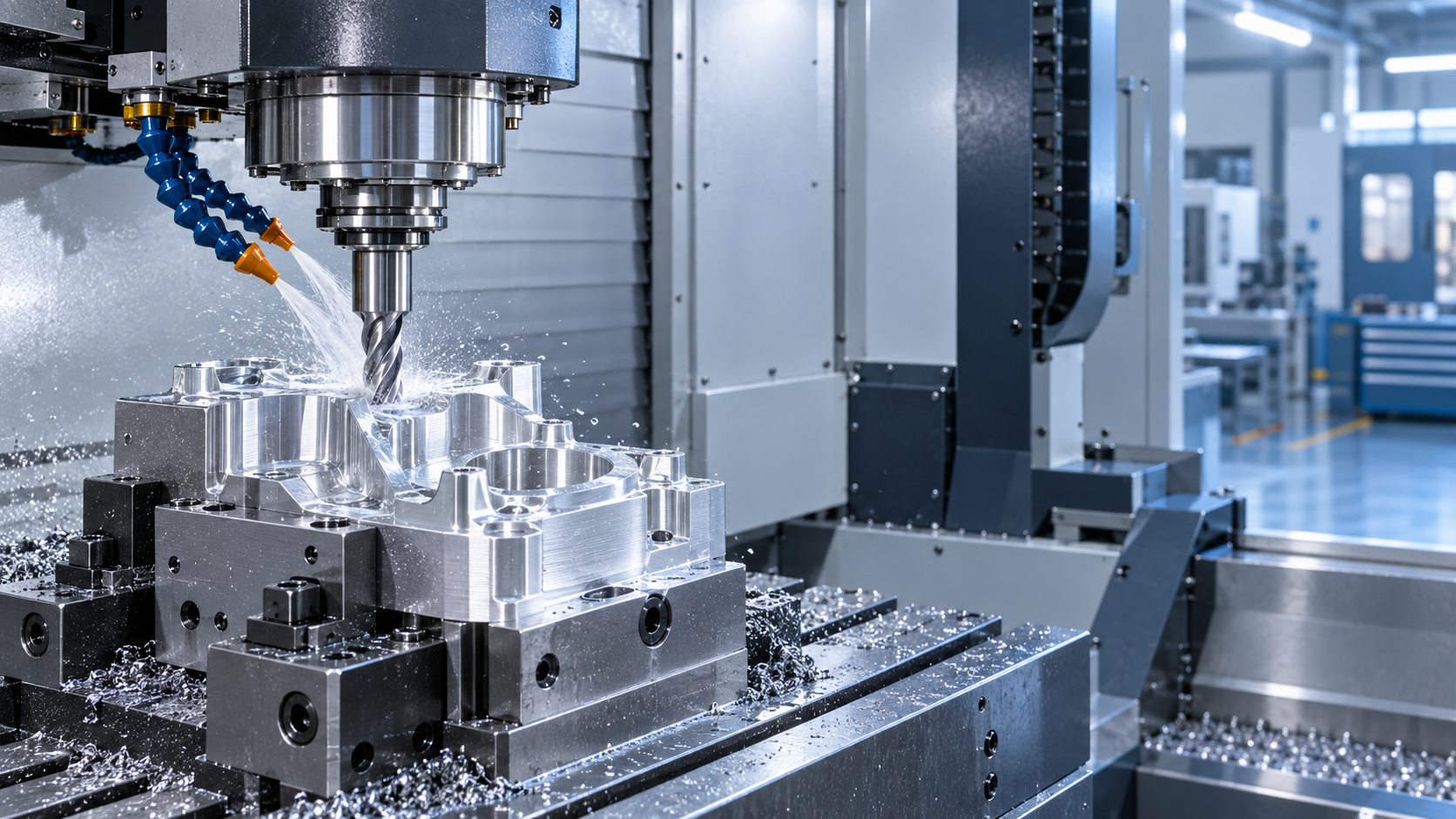
Do not immediately change spindle speed or feed rate after finding a poor finish. First document where the defect appears, its direction, frequency, and consistency.
Uniform scratches running along the tool path usually indicate tool wear, chip recutting, contamination, or an inappropriate finishing pass. Random marks often point to chips or clamping issues.
Repeating waves at regular intervals are commonly associated with chatter. Inspect the cutter overhang, toolholder condition, fixture rigidity, spindle bearings, and machine mounting condition.
A dull, smeared surface is different from chatter. It often results from aluminum adhering to the cutting edge, insufficient lubrication, excessive heat, or unsuitable tool geometry.
Quality inspectors should record defect location by feature type. Compare flat faces, pockets, bores, thin walls, and external profiles because each geometry responds differently to cutting loads.
This record helps prevent broad parameter changes that improve one feature while making another feature worse. It also creates useful evidence for corrective-action reviews.
Check Tool Material, Geometry, and Wear First
Tooling is usually the fastest place to find a correctable cause. Aluminum requires sharp cutting edges, polished flutes, and geometry that evacuates chips efficiently.
For finishing common aluminum alloys, polished carbide end mills with two or three flutes are often effective. More flutes are not automatically better.
Too many flutes can reduce chip space, particularly in pockets or deep cavities. Poor chip evacuation increases heat, causes recutting, and leaves streaks across finished surfaces.
Inspect cutting edges under magnification when possible. A tool may still cut dimensions correctly while microscopic edge damage creates tearing, burr formation, and unacceptable reflectivity variation.
Built-up edge deserves special attention. Aluminum can weld to a cutting edge when heat rises, lubrication is weak, or cutting speed and chip load are poorly balanced.
Once material adheres to the tool, the effective geometry changes. The cutter begins rubbing and dragging instead of shearing, making the finish progressively worse.
Establish a documented tool-life limit for critical finish operations. Replace tools based on observed finish capability and wear data, not only after visible breakage or dimensional failure.
Balance Spindle Speed, Feed Rate, and Chip Load
Incorrect cutting parameters are a frequent source of VMC650 aluminum finishing problems. The correct combination depends on alloy, tool diameter, flute count, engagement, and machine condition.
Running too slowly may encourage rubbing and built-up edge. Running too quickly without proper feed can also reduce chip thickness and create heat through excessive edge contact.
Feed rate should be evaluated as chip load per tooth rather than as an isolated number. A stable chip load helps the cutting edge shear aluminum cleanly.
For a finishing pass, reduce radial engagement before reducing feed excessively. A light, controlled finishing cut often improves appearance without forcing the tool to rub.
Quality personnel should compare actual programmed feed with the machine override setting. Temporary operator overrides can hide a process issue and make results difficult to reproduce.
Use controlled trials with one parameter change at a time. Record spindle speed, feed, axial depth, radial step-over, tool condition, coolant method, and finish measurement results.
This disciplined approach reveals a stable operating window. It is more reliable than adjusting several variables after each rejected part and relying on visual judgment alone.
Improve Coolant Delivery and Chip Evacuation
Coolant on aluminum is not only about temperature control. It supports lubrication, reduces material adhesion, carries chips away, and helps protect the finished surface from recutting.
Verify that coolant reaches the actual cutting zone rather than striking the tool shank or pocket wall. Nozzle position can change after maintenance, crashes, or fixture replacement.
In deep pockets, conventional flood coolant may not remove chips effectively. Consider through-tool coolant, directed nozzles, air blast, or programmed chip-clearing moves where appropriate.
However, air-only strategies require careful safety controls. Fine chips can become airborne, contaminate surrounding work areas, and increase exposure risks for operators and inspectors.
Check coolant concentration and cleanliness. Dirty coolant containing fines can act as an abrasive, while weak concentration may provide insufficient lubricity for demanding finishing operations.
Chip control also depends on the tool path. Avoid leaving chips trapped at corners, around bosses, or inside deep cavities where the cutter can pull them across the surface.
For safety managers, recurring chip accumulation should trigger a review of guarding, housekeeping procedures, coolant maintenance, and operator access during cycle interruptions.
Confirm Workholding and Machine Rigidity
A perfectly selected cutter cannot produce a consistent finish if the workpiece moves. Aluminum parts are especially vulnerable when thin walls, broad faces, or unsupported features are machined.
Inspect fixture contact points, clamp force, parallels, locating pins, and jaw condition. Excessive clamp force can distort soft aluminum, while insufficient force allows micro-movement during finishing.
Machine rigidity matters equally. Check whether chatter occurs only at certain table positions, spindle speeds, tool lengths, or directions of cut on the VMC650.
Long tool overhang magnifies vibration. Shortening the cutter extension, using a more rigid holder, or reducing radial engagement can often improve finish without reducing productivity significantly.
Inspect toolholders for taper damage, contamination, poor pull-stud condition, and runout. Even minor runout makes one flute carry more load and leaves an uneven surface pattern.
Periodic machine checks should include spindle condition, axis backlash, guideway lubrication, leveling, and fastening integrity. These items protect both surface quality and predictable machine operation.
Review CAM Tool Paths and Finishing Strategy
Programming decisions strongly affect finish quality. A roughing tool path should not be expected to create a cosmetic surface, even when the part remains within dimensional tolerance.
Use a dedicated finishing pass with stable stock allowance. Uneven residual material causes changing cutting forces, which can create witness lines, chatter, and inconsistent surface texture.
For wall finishing, climb milling is often preferred because it can reduce rubbing and improve consistency. The best approach still depends on fixture stiffness and machine condition.
Maintain a consistent finishing direction on visible surfaces when possible. Reversing tool direction across adjacent areas may produce differences in reflected light despite similar roughness readings.
Corner transitions require special attention. Abrupt changes in engagement can overload the cutter, create dwell marks, and leave burrs that require risky manual deburring work.
Review lead-in, lead-out, ramping, and smoothing settings in the CAM program. Poor entry moves can leave visible marks that are mistakenly blamed on the machine or tool.
Where tapping or secondary drilling is needed outside the machining center, ensure finishing controls remain consistent. For industrial drilling tasks, the VD13RE offers 0-700 r/min speed control and 11000N magnetic force for stable magnetic drilling applications.
Build a Quality-Control Response Plan for Recurring Finish Defects
Visual inspection alone is not enough for recurring aluminum finish problems. Define acceptance criteria using surface roughness values, reference samples, defect photographs, and feature-specific requirements.
Measure roughness at consistent locations and orientations. A part may appear acceptable under one lighting condition while failing functional or cosmetic requirements under another inspection method.
Create a simple escalation process. Operators should identify abnormal finish early, quarantine affected parts, preserve the tool, and record the active program and machine settings.
Quality teams can then compare the defective sample with the last accepted part. This reduces guesswork and helps identify whether the change began after a tool, material, fixture, or program event.
For high-risk components, link finish checks to dimensional inspection. A degraded surface can signal excessive vibration or tool deflection before a bore size, flatness, or positional tolerance fails.
Safety personnel should review any corrective action involving manual polishing, deburring, or rework. These activities can introduce sharp edges, repetitive motion risks, and inconsistent part quality.
Conclusion: Use Surface Finish as a Process-Control Signal
Surface finish problems on aluminum machined by a VMC650 should be treated as measurable process signals, not merely cosmetic defects requiring rework.
Start with the defect pattern, then verify tool condition, cutting parameters, coolant delivery, chip evacuation, workholding, machine rigidity, and CAM strategy in a controlled sequence.
For quality control and safety managers, the strongest result is a documented process window that produces repeatable finish quality while reducing scrap, manual handling, unstable chips, and operator exposure.
When finish standards, inspection data, preventive maintenance, and operator response procedures work together, aluminum machining becomes more predictable, safer, and easier to improve.

Vedon
Typically replies within minutes
Any questions related to Home?

William / CEO / Brand Founder

Jaye / Sales Director