


Gantry Machining Center Setup for Large Weldments Prone to Distortion
Gantry Machining Center Setup for Large Weldments Prone to Distortion
A large welded frame can look stable on the machine table and still move as soon as the clamps are released. Welding residual stress, uneven section thickness, and material removal all influence the final geometry. A properly planned gantry machining center setup must therefore do more than hold the structure firmly: it must avoid forcing the weldment into a shape it cannot maintain.
For machine bases, fabricated housings, and long structural frames, the useful question is not simply whether the machine can reach every surface. It is whether the complete process can deliver the required geometry in the inspection and assembly condition, without repeated straightening or corrective machining.
Establish the acceptance condition before choosing the fixtures
Start with the drawing, datum scheme, and intended support condition. A frame inspected on specified pads may behave differently from the same frame resting across a machine table. Flatness measured while heavily clamped does not prove that the structure will remain flat after unloading.
Confirm which surfaces control assembly, where the component will be supported, and whether tolerances apply in a free or restrained condition. If the drawing leaves this unclear, resolve it before programming. Otherwise, machining and inspection teams may produce different answers while each follows a seemingly reasonable method.
Check the incoming weldment against that plan. Record bow, twist, and available machining stock at critical locations. A high corner is not automatically excess stock; it may indicate that the entire frame is twisted. Establishing a best-fit orientation before cutting can prevent one mounting pad from cleaning up while another runs out of allowance.
Treat stress relief as a process decision, not a checkbox
Where material specifications and fabrication requirements permit, thermal stress relief may be appropriate before machining. Its suitability and cycle depend on the material, weld procedure, section thickness, and required properties. Do not apply a generic temperature-and-hold recipe to every fabricated structure.
For demanding tolerances, consider whether rough machining should precede a further stabilization step. Removing substantial stock can redistribute residual stress even after an earlier treatment. This does not mean every weldment needs two treatments; it means the route should reflect distortion risk rather than habit.
Cooling or waiting between operations helps temperatures equalize, but elapsed time alone does not demonstrate that residual stress has been adequately relieved. Keep thermal settling and stress relief separate in the process plan.
Support the structure without straightening it with clamps
A practical starting point is three primary supports establishing the setup plane, with adjustable auxiliary supports beneath areas exposed to cutting loads. On a flexible weldment, those auxiliary supports should meet the workpiece without jacking it into a new shape. Their positions need to follow the structural load paths, not merely convenient gaps between table slots.
Place clamps close to supported, relatively stiff regions such as ribs or section intersections. Clamping a thin flange midway between supports can bend it downward; machining it flat in that condition may leave a raised area when released. More clamp force is not necessarily more stability.
Use a controlled tightening sequence and monitor accessible reference points with indicators. If those points move materially during tightening, investigate the support arrangement before increasing force. Provide positive resistance to cutting loads where needed instead of relying solely on friction and excessive clamp pressure.
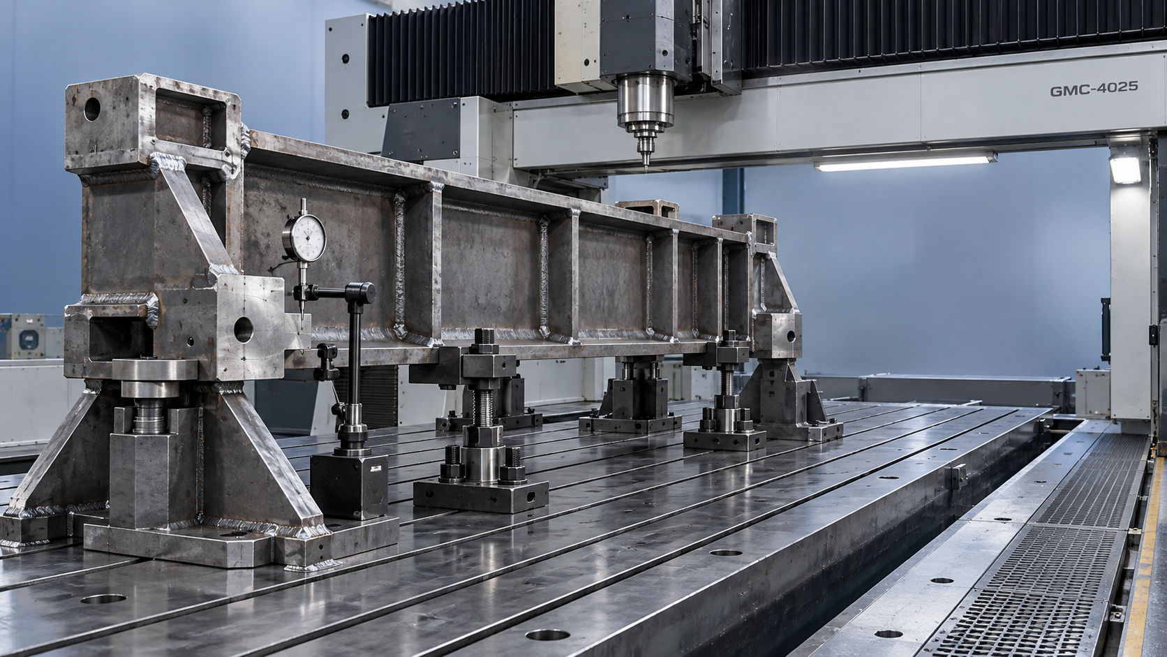
The setup record should identify primary supports, auxiliary supports, clamp locations, and tightening order. This is especially valuable when roughing and finishing use separate setups: a photograph alone rarely explains which jack was carrying load and which was only touching.
Check the working envelope with the actual tooling installed
A gantry machining center may have sufficient nominal travel yet still lack clearance around a tall fixture, extended toolholder, or side-access operation. Verify the combined workpiece and fixture mass against machine limits, then check head clearance, tool-change space, probing access, and chip removal. Include any angle head or long-reach tooling in the collision review.
Clean scale, weld spatter, and burrs from support and reference locations. Probe or indicate enough points to understand the geometry rather than aligning from one convenient welded edge. Where possible, create durable reference features early so subsequent setups do not depend on irregular fabrication surfaces.
Shandong VEDON Intelligent Equipment Co., Ltd. supplies CNC machine tools, intelligent manufacturing solutions, and precision cutting tools. For this application, a useful technical discussion should connect machine capacity and tooling reach with the proposed support layout and machining sequence—not stop at whether the weldment fits on the table.
Separate stock removal from final geometry
Roughing should leave enough material for correction after the structure moves. Determine that allowance from the incoming geometry, fabrication history, and tolerance requirements rather than using one fixed value for every job.
Where access permits, distribute stock removal across related surfaces instead of completing one heavily machined face while leaving the opposite region untouched. Machine paired mounting areas in a sequence that limits unbalanced removal. The objective is not perfect symmetry at any cost; it is to avoid creating an unnecessarily large change in stiffness or stress balance during one operation.
After roughing, include a planned release-and-recheck stage. Secure the workpiece against movement before relaxing clamps, then re-establish support and alignment using the documented method. Compare reference measurements before deciding whether the remaining stock is sufficient for finishing.
For cutting parameters, tool-manufacturer recommendations are a starting point, not proof that a flexible weldment will remain stable. Limit tool overhang, use sharp cutting edges suited to the material, and adjust engagement where local stiffness changes. Chatter near an unsupported wall is often a support problem, not simply a spindle-speed problem.
Keep secondary drilling from disrupting the main setup
Some noncritical auxiliary holes may be better handled outside the gantry cycle, provided their location tolerance and accessibility allow it. The VDG50 magnetic drill has a listed maximum drilling diameter of 50 mm, 1500 W rated power, and 12000 N magnetic-base suction force. It is a separate drilling tool, not a substitute for coordinate-controlled machining of precision bores.
Magnetic holding depends on suitable ferromagnetic material, thickness, flatness, and surface condition. The listed suction force should not be treated as guaranteed holding force on a painted, scaled, or thin welded surface. Follow the operating instructions and use the specified secondary restraint.
Release the part before declaring the process successful
Finish inspection should reproduce the agreed support condition and account for temperature differences across the structure. An on-machine probe can confirm geometry in the current setup, but it cannot by itself establish what happens after unclamping.
Build schedule allowance around inspection gates: incoming stock confirmation, post-roughing movement, and final released geometry. If the frame springs beyond tolerance after release, the next action is to review support loading, residual stress, and removal sequence—not automatically take another finishing pass in the same distorted setup.

Vedon
Typically replies within minutes
Any questions related to Home?

Elaine / Sales Director

Jaye / Sales Manager

Jessica / Sales Manager