How VMC650 Travel, Table Load, and Spindle Power Shape Part Capability
A machining schedule can look feasible until the first part is placed on the machine. A housing may fit within the drawing envelope but exceed the practical working area once fixtures, clamps, and tool clearance are included. A steel plate may fit on the table but create unstable cutting conditions because its mass and overhang change the machine’s dynamic behavior. In these situations, the VMC650 specification is not a catalog detail: it determines whether the part can be produced predictably.
The core judgment is straightforward. Travel defines the usable machining envelope, table load defines what can be supported safely and stably, and spindle power determines how aggressively material can be removed. A VMC650 can be an efficient choice when all three limits align with the finished part, the workholding method, the material, and the required cycle time. It becomes a poor fit when one constraint is treated in isolation.
Travel is the first limit, but not the finished-part size
Machine travel is often read as a direct statement of maximum part dimensions. That is only partly true. X-, Y-, and Z-axis travel describe how far the spindle can move relative to the table; they do not automatically represent the maximum practical workpiece envelope.
Consider a rectangular component that appears to fit inside the X-Y travel range. Before approving the machine, the team still needs space for vises, locating blocks, toe clamps, fixture plates, and tool approach paths. A part may also require machining on several faces, which can introduce rotary fixtures or repositioning requirements. Each addition consumes available space and may restrict axis movement near the ends of travel.
Z-axis capacity needs the same discipline. The available vertical distance must accommodate the fixture height, raw stock thickness, toolholder length, cutting tool projection, and clearance needed for safe tool changes or rapid positioning. Deep pockets and tall side walls can create a situation where the spindle reaches the feature but lacks rigidity because the tool must extend too far from the holder.
Plan around the machining setup, not the drawing outline
For capability review, use the full setup stack rather than nominal finished dimensions. Start with the raw blank, then add fixture thickness and clamping access. Identify the longest tool needed for deep features and calculate whether adequate clearance remains above the workpiece. Finally, review whether every feature can be reached without moving the part into a new setup.
- Allow room for clamps and fixture hardware beyond the part perimeter.
- Check whether critical features are near the travel endpoints, where fixture interference can become more likely.
- Confirm that probe access, tool-change clearance, and chip evacuation are not blocked by a tall setup.
- Separate “can reach the feature” from “can machine the feature with a rigid tool condition.”
This distinction matters most on parts with multiple deep cavities, long side features, or tight positional tolerances between faces. A machine that requires repeated refixturing may still produce the part, but it adds handling time and creates more opportunities for datum transfer error.
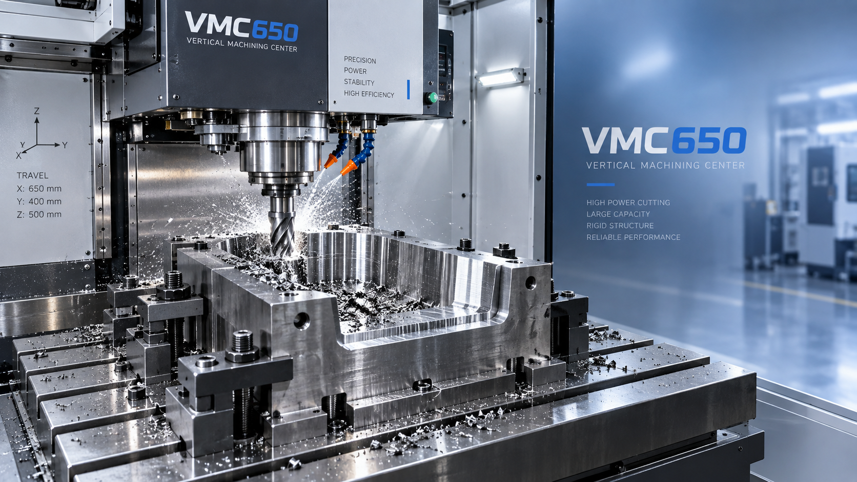
Table load affects accuracy as well as safety
Table load is sometimes treated as a simple weight limit. In practice, the total mass is only the starting point. The machine must support the workpiece, fixture, clamps, pallets, and any auxiliary devices. More importantly, that mass must be positioned in a way that does not create excessive bending moment or imbalance.
A compact, centered workpiece generally places a different demand on the table than a long casting with most of its weight extending beyond one side. Even when both assemblies have the same mass, the overhung setup can affect motion response, load distribution, and repeatability during rapid traverses. This is especially relevant when machining one end of a long component or when a fixture base occupies much of the table.
For a VMC650 evaluation, record the actual setup weight rather than only the finished part weight. Include the heaviest expected blank, not the lightest production version. Then examine the center of gravity. A setup near the table center is usually easier to manage than one shifted toward an edge, but the final decision must follow the machine builder’s load and placement limits.
Weight can become a process problem before it reaches a rated limit
Heavy workholding may reduce usable Z clearance and make loading slower. It can also encourage a team to use a single large fixture for a family of parts, even when a lighter modular arrangement would provide better access. Conversely, an undersized fixture may keep table mass low but fail to resist cutting forces, causing vibration or movement at the locating surfaces.
Assess the fixture as part of the machining system. The relevant question is not merely whether the table can carry it, but whether the complete assembly remains stable while the spindle is accelerating, changing direction, and cutting at the required removal rate.
Spindle power sets the realistic material-removal window
Spindle power influences how much material can be removed per pass, how well the machine handles demanding materials, and how much cycle-time margin exists when tools begin to wear. It should not be confused with a guarantee of cutting performance. Power works together with spindle torque, speed range, tool diameter, cutter geometry, coolant delivery, and machine rigidity.
Aluminum components may permit high feed rates and wider engagement when the toolpath and chip evacuation are appropriate. Carbon steel, stainless steel, alloy steel, and tougher cast materials generally require more careful control of cutting force and heat. A spindle with limited power may still machine these materials successfully, but the process may need reduced depth of cut, narrower radial engagement, lower feed rates, or more passes. Those choices affect cycle time and tool consumption.
Project planning becomes difficult when the estimated cycle is based on ideal cutting parameters while the actual machine must operate at reduced engagement to avoid overload. The difference can be substantial across a batch of parts, particularly when roughing dominates the cycle. Review roughing and finishing separately: roughing normally drives power demand, while finishing often depends more on tool runout, machine stiffness, thermal behavior, and consistent spindle speed.
Capability should be reviewed as a combined operating envelope
A part can fit within travel limits, remain below the table-load rating, and still be inefficient to machine because the spindle lacks the power needed for the planned roughing strategy. The opposite can also happen: a powerful spindle does not solve a travel shortage, an inaccessible feature, or a fixture that creates excessive overhang.
A practical review begins with the part model and routing. Identify the largest raw stock condition, the number of required orientations, the fixture concept, the deepest and widest features, and the material condition. Then establish the most demanding operation. It may be face milling a large surface, roughing a pocket, drilling a large diameter, or using a long end mill on a deep wall. That operation is where travel, load, and power should be checked together.
- Map every required feature to a spindle orientation and fixture position.
- Calculate the assembled weight of blank, fixture, clamps, and accessories.
- Check the center of gravity and any planned overhang against the machine documentation.
- Build the Z-axis stack using the longest realistic toolholder and tool combination.
- Estimate cutting demand for the heaviest roughing operation using the intended material and cutter.
- Review whether the proposed cycle time still works after allowing for tool wear, inspection, loading, and repositioning.
Do not let secondary operations hide a capacity gap
Some parts require holes, slots, or site work that cannot be completed in the machining center because of part size, assembly stage, or access constraints. Separating those operations can be sensible, but it should be deliberate. For example, a portable magnetic-base core drill such as VD50EZ may support controlled hole-making work where a suitable ferrous mounting surface is available. Its stated 50 mm maximum core drilling diameter, 1500 W rated power, 0–600 r/min no-load speed, and 13000 N magnetic base suction describe a different operating role from a VMC650.
That distinction is important in planning. A portable drilling tool can address an access-specific operation, but it does not replace machining-center positioning accuracy, fixtured repeatability, or multi-axis feature relationships. When holes must be located tightly relative to milled datums, the preferred route is usually to retain those features in the CNC setup whenever travel and workholding permit it.
Questions to settle before releasing the machine plan
Before committing the VMC650 to a part family, ask whether the largest production blank—not just the nominal part—fits with its fixture. Confirm whether the heaviest setup stays within approved table-load and placement conditions. Review the longest tool required, because a deep feature may be technically reachable but economically poor to cut. Finally, compare the spindle’s usable power range with the actual roughing load for the hardest expected material condition.
These checks turn catalog specifications into a usable production decision. They also prevent a common schedule problem: discovering after fixture build that the part fits physically, yet cannot be machined with the desired stability, cycle time, or feature access.

Vedon
Typically replies within minutes
Any questions related to Home?

William / CEO / Brand Founder

Jaye / Sales Director