How to Control Chatter When Using a Vertical Milling Machine on Steel
Chatter in steel milling is not a minor sound issue. Once vibration starts, it can leave repeated marks on the cut surface, push dimensions out of tolerance, chip cutting edges, loosen workholding, and create a higher risk of tool breakage. On a Vertical Milling Machine, the fastest way to regain stability is usually not to change only one setting. The practical approach is to identify the weak link in the cutting system: tool projection, cutter engagement, workholding, spindle condition, or machine rigidity.
A useful rule is to avoid making large speed and feed changes before checking the setup. Steel chatter often occurs because the tool, workpiece, and machine structure are amplifying each other at a certain frequency. Reducing spindle speed may help, but it can also increase rubbing if the chip load becomes too low. First confirm that the tool is cutting properly and that the setup is rigid enough for the intended depth and width of cut.
Recognize the Difference Between Chatter and Other Milling Problems
Chatter usually produces a sharp, uneven sound that rises and falls during the cut. The machined surface may show evenly spaced waves, diagonal marks, or a repeating pattern that is different from normal tool marks. Vibration may become more obvious near corners, thin walls, deep pockets, or when the cutter enters a wide engagement zone.
Not every noisy cut is chatter. A dull cutter can squeal because it rubs rather than shears. Poor chip evacuation can cause chips to be recut, producing noise and surface damage. An interrupted cut may create a rhythmic impact that is normal at low levels but becomes unstable when the tool is extended too far. Before changing parameters, inspect the finished surface and listen for whether the sound is continuous, periodic, or tied to a specific point in the toolpath.
Start With the Cutter and Toolholder
Excessive tool overhang is one of the most common causes of chatter when machining steel. Every extra length between the spindle nose and the cutting edge reduces stiffness. A long end mill can flex even when the machine itself is in good condition. Use the shortest practical gauge length, and ensure that the tool is seated correctly in a clean holder.
- Select the largest tool shank diameter that the feature allows.
- Minimize stick-out from the collet, hydraulic holder, or milling chuck.
- Check that the collet and holder taper are clean, undamaged, and fully seated.
- Replace worn end mills rather than compensating with lower feed rates alone.
- Choose a flute count that suits the cut and chip space required for the steel grade.
For many steel milling operations, a variable-pitch or variable-helix end mill can reduce harmonic vibration because the cutting edges do not enter the material at identical intervals. This does not correct weak workholding or a damaged spindle, but it can make a stable setup more tolerant of demanding cuts. Coating, corner preparation, and edge geometry should also match the material condition. A tool intended for mild steel may not perform the same way in hardened, scaled, or work-hardened material.
Adjust Speed and Feed Without Causing Rubbing
When chatter begins, operators often reduce feed first. That can make the problem worse. If feed per tooth falls below the level needed for the cutting edge to form a proper chip, the edge rubs and generates heat. The resulting vibration may sound smoother at first, but tool wear and poor surface finish can increase.
A better first adjustment is often a moderate spindle-speed change while maintaining a realistic chip load. Move the speed enough to shift the system away from the vibration frequency rather than making a very small change. In practice, a reduction or increase of roughly 10% to 20% can be a sensible trial, provided the resulting cutting speed remains appropriate for the tool and steel grade. Observe the sound, spindle load, chip shape, and surface finish after each controlled adjustment.
Radial engagement has a major effect on stability. A full-width slot places high and changing loads on the cutter. Where programming allows, use a lower radial step-over with a controlled axial depth, keeping the cutter engaged more consistently. Adaptive or trochoidal paths can reduce sudden load spikes, especially in deeper steel pockets. Do not increase axial depth simply because radial engagement has been reduced; confirm that the available spindle power, tool length, and fixture stiffness support the new cut.
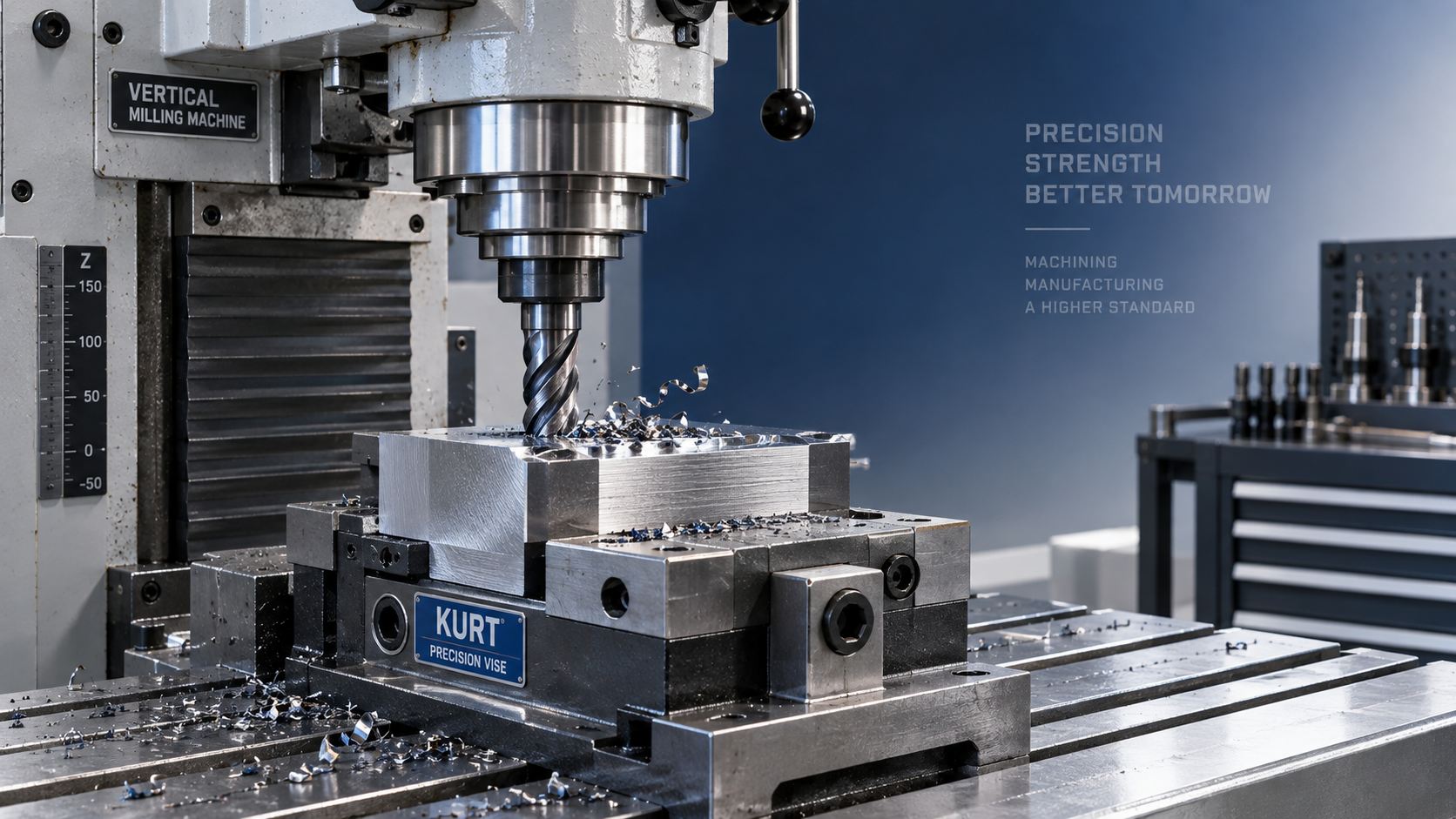
Make Workholding Part of the Chatter Investigation
A rigid cutter cannot compensate for a vibrating workpiece. Steel parts that appear solid can still flex when clamped poorly, especially plates, brackets, thin sections, and parts with long unsupported edges. Chatter may occur only at one end of the component because that section is less supported than the rest.
Check whether the part is sitting flat on clean parallels, fixture pads, or the machine table. Chips trapped under the workpiece can create a rocking condition that is not obvious until cutting force increases. Clamps should apply force close to the cutting area without obstructing the toolpath. Over-tightening a thin part can distort it before machining, while insufficient support allows it to vibrate during the cut.
For recurring operations, consider whether additional support points, a dedicated fixture, or a change in machining sequence would improve stability. Roughing one side of a thin component before adequate support is added can release stress and reduce rigidity for later finishing passes. Milling near a clamp can also behave differently from milling over an unsupported cavity, so parameter changes may need to follow the changing stiffness of the part.
Inspect the Machine Before Blaming the Program
On a Vertical Milling Machine, loose mechanical elements can turn an otherwise acceptable process into an unstable one. Check drawbar retention, spindle taper cleanliness, toolholder condition, table locks, vise mounting, and gibs or guideway adjustment according to the machine manufacturer’s procedure. A loose vise, worn fixture key, or poorly seated holder can create chatter that resembles an incorrect cutting parameter.
Spindle condition deserves particular attention when vibration occurs with multiple tools and different workpieces. Unusual spindle noise, heat, excessive runout, or changing vibration at the same speed range may indicate a maintenance issue. Tool runout can overload one flute, causing uneven chip formation and premature wear. Measure runout at the tool when the process is sensitive, rather than assuming a new cutter is automatically running true.
Keep the machine table and fixture interfaces clean. A single chip beneath a vise or fixture can reduce contact stability. Confirm that unused axes are locked when appropriate for the machine and operation, but do not force locks or adjustments beyond the equipment instructions. Lubrication, way condition, and backlash can also affect finish during direction changes or fine finishing passes.
Control Chip Flow and Entry Conditions
Steel chips that remain in the cut can be pulled back into the tool, especially in slots, deep pockets, and blind features. Recutting chips raises cutting force and may trigger chatter after the operation has been stable for part of the cycle. Use coolant, air blast, or another suitable chip-clearing method compatible with the material, tool, and shop safety requirements. The objective is to clear chips without directing them toward people or leaving them packed around the cutter.
Tool entry also matters. Plunging directly into steel with an end mill that is not designed for center cutting can shock the tool and start vibration. Ramping, helical entry, or a pre-drilled entry point may produce a more stable transition. Where holes must be prepared before milling, a magnetic drilling unit such as the VDD80 may be suitable for industrial drilling work on compatible ferrous surfaces; its role is hole preparation, not replacement of milling-machine rigidity or proper milling parameters.
Verify the Fix Through a Controlled Trial
After making an adjustment, run a short controlled pass rather than immediately returning to a full production cycle. Compare the sound, surface pattern, chip formation, tool condition, and part stability. Change one primary variable at a time whenever possible. If speed, feed, tool projection, workholding, and toolpath are all altered together, it becomes difficult to identify what actually solved the problem.
When chatter persists across different cutters, parts, and parameter ranges, stop treating it as a routine cutting adjustment. Repeated vibration can damage tools, fixtures, spindle interfaces, and the workpiece. At that point, a closer inspection of spindle runout, bearing condition, machine alignment, fixture design, and programmed cutter engagement is justified before the defect becomes a recurring safety and quality issue.

Vedon
Typically replies within minutes
Any questions related to Home?

William / CEO / Brand Founder

Elaine / Sales Manager

Jessica / Sales Manager