Vertical Milling Machine Safety Checks Before Heavy Slotting Operations
Vertical Milling Machine Safety Checks Before Heavy Slotting Operations
Heavy slotting is one of those milling operations that can look routine on a program sheet and become unforgiving at the machine. A wide cutter engaging deeply in solid material produces sustained radial load, concentrated heat, large chip volumes, and a stronger tendency for chatter than light face milling or finishing passes. If something is marginal—a loose fixture, damaged pull stud, worn toolholder taper, weak coolant flow, or a guard that does not latch correctly—the first roughing pass may expose it quickly.
For a Vertical Milling Machine, the pre-operation check should therefore be more than a quick visual walk-around. It is a practical decision point: is the machine, setup, and cutting plan genuinely stable enough for the planned width and depth of cut? The objective is not simply to avoid an incident. It is to keep the slot straight, protect the spindle and fixture, prevent unexpected tool breakage, and avoid scrapping a workpiece after most of its value has already been added.
Start with the Job, Not the Machine
A reliable inspection begins by reviewing what the cutter will actually do. Confirm the workpiece material, slot dimensions, stock condition, cutter diameter, programmed spindle speed, feed, step-down, and coolant strategy. This matters because “heavy” is relative. A full-width slot in alloy steel places very different demands on a machine than a shallow channel in aluminum, even if both use the same end mill diameter.
Pay particular attention to tool engagement. A programmed toolpath may create a full-slot condition at entry, in a corner, or when machining remaining material around a feature. If CAM simulation is available, review engagement rather than assuming the nominal radial depth tells the whole story. Quality teams often see the result later as a slot-width variation, taper, poor floor finish, or a mismatch between the first and last parts. Those are not always inspection problems; they can be early evidence that the milling setup was moving under load.
The approved setup sheet should also identify the cutter and holder combination. Substituting a longer holder, a different collet system, or a tool with more overhang may seem harmless if the nominal diameter is unchanged. In heavy slotting, it can change rigidity enough to require revised cutting conditions.
Verify Rigidity from the Foundation Up
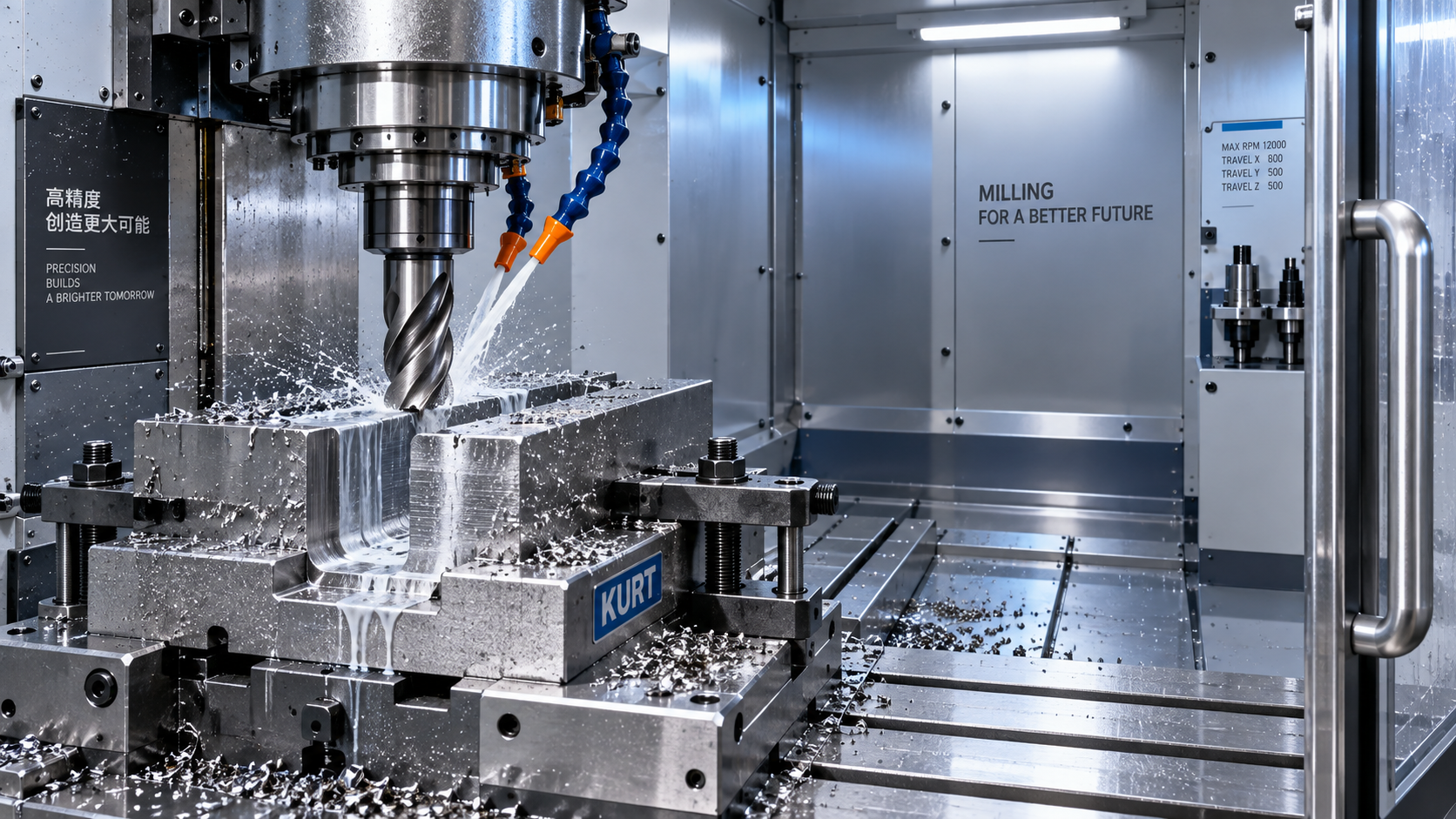
Before checking the spindle, look at the foundation of the cut: the workholding. The vise, fixture plate, clamps, parallels, locating pins, and workpiece support must resist cutting force in every relevant direction. A clamp that clears the cutter but permits the part to lift or pivot is not an acceptable clamp. On thin or irregular components, support beneath the slotting area deserves special attention. The part may be secure at both ends yet flex in the middle as the slot approaches full depth.
Confirm that the fixture is seated on a clean table surface and that chips have not been trapped under locating faces. Check visible fasteners for correct seating and condition, using the fastening method and torque practice specified by the fixture or machine documentation. Do not rely on an operator’s feel alone where a controlled procedure is required. If the job uses soft jaws, verify that their gripping surfaces match the current part revision and that jaw screws are not bottoming out before clamping force is reached.
The machine table and axis motion also need a realistic check. With the machine in a safe state, inspect for abnormal noise, backlash symptoms, stick-slip, or unusual vibration during a controlled low-load movement. A worn way cover, loose cable carrier, or accumulated swarf may not directly cause poor slot geometry, but it can interfere with travel or conceal a developing maintenance issue. Any abnormality should be evaluated before a high-load cycle begins, not explained away after it alarms.
Tooling and Spindle Checks Carry the Highest Consequence
Inspect the cutting tool under adequate light. Look for chipped cutting edges, built-up edge, uneven wear, discoloration from overheating, damaged coating, and packed chips in flutes. A tool can still cut after its edges have deteriorated, but it may require more force and generate more heat. During slotting, that increase can become a feedback loop: chip evacuation worsens, torque rises, vibration begins, and the tool fails or pushes the slot out of tolerance.
Clean the taper interface, toolholder, retention knob or pull stud, and spindle taper according to the machine maker’s approved practice. Damage or contamination at this interface can compromise concentricity and clamping security. Check that the tool projection is only as long as needed for clearance. Excess projection is a frequent, avoidable source of chatter. Where runout limits are defined by the tool manufacturer or internal process plan, measure and record them rather than judging by appearance.
For automated tool changes, inspect the selected magazine pocket, tool data, and interference clearance. A large-diameter cutter or extended holder may require an empty adjacent pocket depending on the machine configuration. This is a small detail with potentially expensive consequences. Verify that the programmed tool number, offset data, and physical tool agree before dry-running or cutting.
Guarding, Interlocks, and Emergency Response Must Be Tested, Not Assumed
Heavy milling throws chips farther and with more energy than many finishing operations. Inspect windows for cracks, clouding, looseness, or damage that limits a clear view of the cut. Door seals, guard panels, chip conveyors, and splash containment should be intact and positioned for the actual coolant volume. If a guard or viewing window has been modified, damaged, or temporarily bypassed, the machine should not be treated as ready for production.
Confirm that access doors close and latch properly, and test safety interlocks only in accordance with the manufacturer’s procedure. Verify the emergency-stop function and ensure the operator can reach it without moving around the machine. The response plan should be equally clear: who stops the process, who isolates energy if intervention is needed, and who authorizes restart after an abnormal event. Clearing a bird’s nest of chips, inspecting a broken cutter, or reaching into the enclosure must never be handled while the spindle or axes can move. Apply the site’s lockout/tagout process and the relevant local requirements.
Coolant, Lubrication, and Chip Control Are Part of the Safety Check
Slotting is often limited by chip removal rather than spindle power. Check coolant level, concentration control method, nozzle aim, pump operation, and filter condition. The goal is to direct coolant into the cutting zone and carry chips away before they are recut. A nozzle aimed at the tool shank may look active while doing little to clear a deep slot. If coolant delivery is insufficient for the material and cutter strategy, reducing cutting parameters or revising the operation may be safer than proceeding with the original cycle.
Review machine lubrication status and alarms before start-up. Low lubrication, leaks, or an overdue maintenance condition should be addressed under the established maintenance process. It is poor practice to run a demanding roughing operation simply because the machine has not yet stopped itself. Also check chip conveyor and auger operation where fitted. Long, stringy material chips can accumulate around fixtures and interfere with probing, tool motion, or enclosure drainage.
Use a Controlled First-Cut Release
A completed checklist does not replace observation during the first part. Run the first engagement at a controlled setting where permitted by the process plan, and listen for changes in cutting sound. A steady cutting tone is not proof of a good process, but sudden ringing, pulsing, squealing, or repeated load spikes warrant a stop and review. Watch chip shape and discharge, coolant reach, spindle load trend where available, and whether chips are collecting in the slot.
Inspect the first slot before releasing the process to normal production. Width, depth, straightness, burr condition, wall finish, and floor finish can reveal different issues. A tapered wall may indicate tool deflection or runout; tearing can point to a worn edge or unsuitable cutting data; an inconsistent width may suggest fixture movement, backlash, or thermal effects. The right response is to identify the cause, not merely compensate with an offset.
Where repeated heavy machining is central to production, it may also be worth assessing whether the part orientation and machine architecture match the work. For example, a Horizontal machining center can offer a different chip evacuation path and workholding approach for suitable components. Models such as the NCH-50 series provide 500 × 500 mm worktables, while listed configurations range from 400 kg to 1,000 kg maximum table load. That does not make horizontal machining automatically preferable; accessibility, part geometry, tooling, and process validation still decide the better option.
Shandong VEDON Intelligent Equipment Co., Ltd. approaches machine tools, intelligent manufacturing solutions, and precision cutting tools around the practical connection between innovation, quality, and reliability. In daily production, that connection is visible in disciplined preparation: a stable setup, verified protection systems, sound tooling, and a first-cut check that is allowed to challenge the plan. Before a heavy slotting cycle, a Vertical Milling Machine should be ready for the forces involved—not merely switched on and available.

Vedon
Typically replies within minutes
Any questions related to Home?

William / CEO / Brand Founder

Elaine / Sales Manager

Jessica / Sales Manager