How to Maintain Magnetic Holding Force When Using a Magnetic Drill VD50
Maintaining reliable magnetic holding force is essential for safe, accurate drilling, especially in demanding industrial environments. When using a Magnetic drill VD50, quality-control and safety professionals must look beyond the magnet switch itself. Workpiece thickness, surface condition, power supply stability, drill position, and operator behavior all affect whether the machine remains securely attached during the cut.
A magnetic drill rarely gives much warning before a holding problem becomes serious. The first signs may be subtle: slight vibration, an uneven cutter mark, a machine that feels less planted than expected, or chips packing around the tool. If those signals are ignored, the drill can shift, damage the workpiece, break the cutter, or create a high-risk situation for the operator. A practical control plan should therefore focus on preventing loss of holding force rather than reacting after movement occurs.
Start with the steel, not the drill
The magnetic base needs a suitable ferromagnetic surface to develop its intended clamping force. This sounds obvious, but it is one of the most common points missed during hurried fabrication, maintenance, and field work.
Before placing the Magnetic drill VD50, confirm that the material is magnetic steel and that it has sufficient thickness for magnetic drilling. Thin plate can become saturated and may not provide the same holding strength as thicker structural steel. If the workpiece is too thin, flexible, or poorly supported, drilling pressure can cause deflection even when the magnet initially appears secure.
Material composition matters as well. Stainless steels, coated panels, painted structures, and composite assemblies may look suitable but can offer little or no magnetic attraction. Do not rely on appearance alone. A quick magnet test is useful, but a documented pre-use check is better for controlled operations.
For thin stock, curved surfaces, or locations close to an edge, the safest answer may be to change the drilling method, add a properly designed support plate where permitted, or use a mechanical clamping arrangement. Trying to “make it work” with a marginal magnetic contact is not a productivity shortcut; it is an uncontrolled variable.
Clean contact is a safety requirement
Magnetic force is weakened by the smallest separation between the base and the workpiece. Rust scale, weld spatter, machining chips, paint, oil film, and burrs all create an air gap. Even a surface that looks reasonably clean from standing height may have enough contamination to reduce effective contact.
Include the following in the pre-drilling inspection:
- Wipe the underside of the magnetic base with a clean, dry cloth.
- Remove loose scale, chips, and weld spatter from the intended mounting area.
- Check for proud welds, seams, holes, or uneven profiles beneath the magnet.
- Degrease excessive oil or coolant residue without introducing moisture under the base.
- Inspect the base face for dents, scoring, or embedded metal particles.
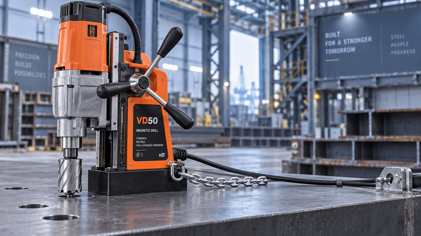
This inspection should not be treated as housekeeping alone. For a quality team, it is a repeatable control point: a clean, flat contact zone supports better positional accuracy and reduces the chance of movement during cutter breakthrough. For safety personnel, it is a direct barrier against drill displacement.
Positioning determines how drilling loads reach the magnet
A magnetic base holds most reliably when the drilling load acts straight down through a stable setup. Poor positioning introduces side load, torque, and leverage that can overcome an otherwise strong magnetic attachment.
Place the drill so the base sits fully on the workpiece, with no portion bridging a gap, edge, flange transition, or irregular weld area. Keep the cutter aligned perpendicular to the surface whenever the application allows. On vertical steel, overhead work, or inclined surfaces, use the supplied safety chain or safety strap as a mandatory secondary restraint. The strap is not evidence that the magnet is weak; it is protection against a loss of power, unexpected surface condition, or accidental dislodgement.
Be especially cautious when drilling near plate edges. The magnetic circuit needs adequate steel beneath the base. If the base is too close to an edge, holding force can fall significantly. Internal procedures should specify a minimum safe placement distance based on the equipment manual and the geometry of the magnet base, rather than leaving that judgment entirely to the operator.
Power stability is part of magnetic holding force
On electrically powered magnetic drills, the magnet depends on a stable supply. A loose extension lead, damaged cable, poor connection, overloaded temporary power circuit, or accidental plug removal can release the base immediately. In mobile work areas, this risk deserves the same attention as cutter selection.
Before operation, inspect the cord, plug, strain relief, extension cable rating, and connection point. Avoid routing cables where they can be pulled by lifting equipment, caught on sharp steel, or exposed to hot slag and coolant. Where site conditions permit, a protected power source and cable management plan reduce avoidable interruptions.
Operators should also understand the machine’s control sequence. The magnet must be energized and checked before the motor starts. If power is interrupted, the correct response is to support the machine safely if possible, isolate the supply, and inspect the setup before restarting. Never assume the drill will remain attached after an electrical fault.
Control feed pressure and cutter condition
Holding force is not only a static issue. It is challenged continuously by drilling forces. A dull annular cutter, excessive feed pressure, poor chip evacuation, or a cutter that catches at breakthrough can pull the machine sideways or make it twist.
Use a sharp, suitable core drill bit and apply steady feed rather than forcing the cut. Let the cutter produce consistent chips. If chips become blue, packed, unusually fine, or irregular, pause and investigate heat, lubrication, speed, and cutter wear. Excessive force may feel faster for a few seconds, but it often creates vibration, reduces hole quality, and increases the load transmitted to the magnetic base.
Breakthrough deserves special attention. As the cutter exits the material, resistance changes abruptly and the slug may release. Reduce feed pressure near completion and ensure the workpiece is stable. On thin material, the moment of breakthrough can be particularly abrupt.
A simple verification routine for quality and safety teams
Rather than relying on individual experience alone, establish a short verification routine before each drilling task or whenever the drill is repositioned:
- Confirm the workpiece is ferromagnetic, adequately thick, and supported.
- Prepare a clean, flat seating area and inspect the magnet face.
- Position the base fully on the steel, clear of edges and uneven features.
- Connect and energize the magnet, then perform a careful manual stability check without applying dangerous force.
- Fit the safety chain or strap for vertical, angled, overhead, and higher-consequence work.
- Verify cutter condition, tool security, cable condition, and suitable drilling parameters.
- Monitor vibration, chip formation, and machine movement throughout the cut.
Documenting these points in a pre-use checklist can reveal recurring causes of nonconformity: a particular coated material, a frequently damaged extension lead, inadequate cleaning tools, or operators placing the drill too near flange edges. The aim is not to burden the job with paperwork. It is to make the critical conditions visible before they become incidents.
When the standard setup is not enough
Some applications require more travel, a larger drilling capacity, or a different machine format. In shipbuilding, oil and gas maintenance, automotive fabrication, and structural metalwork, the correct drill should be selected around the material, hole size, access, and orientation—not simply availability on the shop floor.
For teams evaluating a larger-capacity option within the same equipment range, the VD60 can be reviewed alongside the VD38, VD40, and VD50 configurations. Rated voltage, drilling diameter, travel, weight, and magnetic-base specifications should always be checked against the actual task and the manufacturer’s current documentation. A larger machine is not automatically safer if its weight, footprint, or access requirements are unsuitable for the work area.
What to do if the drill begins to move
Stop feeding immediately. If it is safe to do so, switch off the motor and keep clear of the machine’s potential movement path. Do not try to hold a shifting drill body by hand while the cutter is rotating. Once the machine is secured and isolated, inspect the seating surface, material thickness, magnet face, power supply, cutter condition, and drill position before resuming.
Repeated movement is a signal to stop the task and reassess the method. Repositioning the same setup without identifying the cause can turn a near miss into an injury or damaged component.
Reliable magnetic holding force comes from disciplined preparation: clean steel, full base contact, stable power, controlled drilling loads, and a secondary restraint where required. When those conditions are checked consistently, the Magnetic drill VD50 becomes easier to control, hole quality becomes more repeatable, and safety decisions are based on evidence rather than assumption.

Vedon
Typically replies within minutes
Any questions related to Home?

William / CEO / Brand Founder

Vinson / Sales Director

Elaine / Sales Manager

Jessica / Sales Manager