How to Select a Universal Milling Machine for Multi-Axis Toolroom Work
Select the machine around the hardest part family, not the largest drawing. Multi-axis toolroom work often combines one-off fixtures, prototype components, repair parts, and short runs with frequent setup changes. A universal milling machine should therefore be judged by how reliably it reaches critical features from practical workholding positions, how quickly it changes from one job to the next, and whether its accuracy remains stable after repeated swiveling, clamping, and thermal cycling.
Begin with the parts that repeatedly create scheduling pressure: angled holes, compound faces, pockets that require several orientations, long workpieces, or components that must be machined from multiple datums. These features determine whether a conventional universal configuration with a swiveling table and vertical head is sufficient, or whether a CNC platform with controlled rotary axes is needed. A machine that handles the nominal envelope but forces awkward re-clamping can lose more time in setup and inspection than it saves in purchase cost.
Define the real axis requirement before comparing machines
The phrase “multi-axis” covers very different work. A three-axis machine with a universal table can position a workpiece at an angle, then cut using linear axes. This suits many toolroom jobs where the angle is fixed for each operation and the part can be inspected between setups. It is a practical choice for drilling, slotting, dovetails, inclined faces, and moderate-complexity fixture work.
Continuous contouring around a part is a different requirement. Blades, impellers, sculptured dies, blended radii, and features that must remain synchronized through rotation need coordinated rotary-axis motion and suitable CAM post-processing. Do not assume that a swiveling head or rotary table automatically creates simultaneous multi-axis capability. Confirm the number of axes under numerical control, whether rotary axes are interpolating axes or indexing devices, and which motions remain available while the spindle is cutting.
Axis travel must be reviewed with the fixture, vise, rotary table, toolholder, and longest tool included. Table travel alone can be misleading because a tall fixture consumes vertical clearance, while a fourth-axis unit reduces usable X travel and may obstruct access at one end of the table. For every representative part, model or sketch the worst machining position: workpiece dimensions, clamp locations, tool projection, spindle-to-table distance, and required approach path. This exposes collisions that a brochure travel figure cannot reveal.
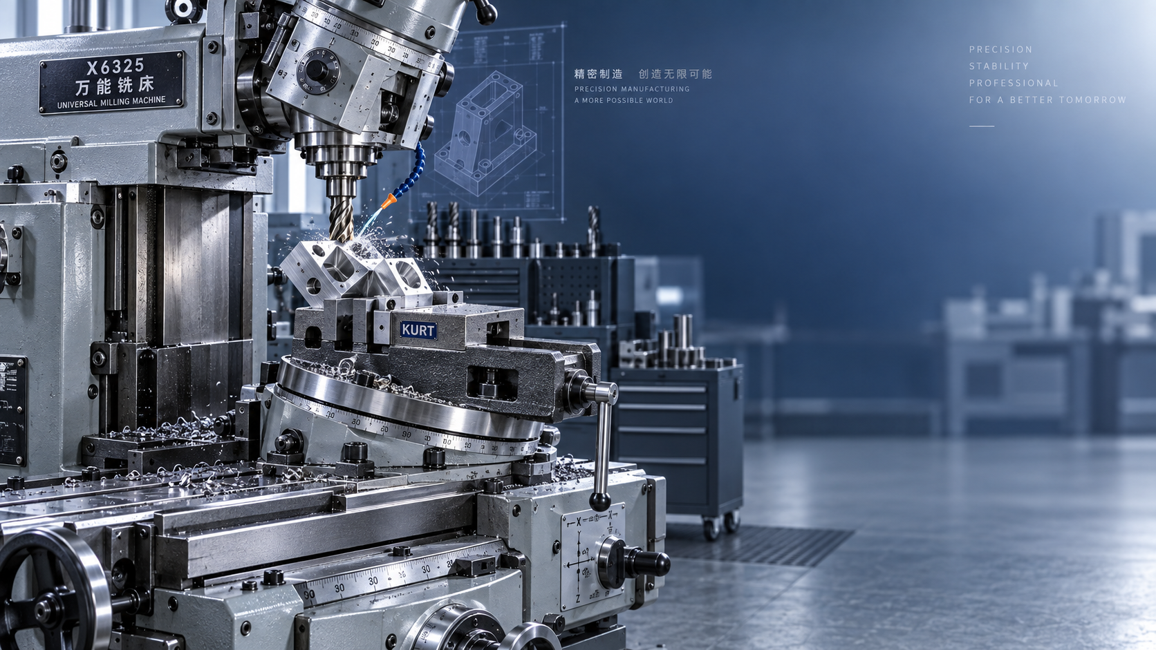
Accuracy has to survive the setup
Toolroom accuracy depends on the complete chain from casting and guideways to spindle, fixture, cutting tool, probing method, and inspection datum. A quoted positioning figure is useful, but it does not describe the final feature error after the table is rotated, a heavy vise is moved, or a long end mill deflects under load. Repeatability often matters more for work involving multiple operations because it governs whether a proven datum can be found again after indexing or a tool change.
Ask for performance evidence under conditions close to the planned workload. A light finishing pass in aluminum reveals little about behavior during interrupted cuts in pre-hardened steel. Evaluate backlash compensation, axis reversal behavior, spindle runout at the actual toolholder interface, and the machine’s ability to retain geometry after warm-up. For universal machines, inspect the locking arrangement of the swivel table and head. A broad clamping surface and positive locking system are meaningful only when the assembly returns consistently to the commanded angle.
Machine rigidity should match both material and cutter strategy. Deep shoulder milling in alloy steel calls for stable spindle support, robust guides, a rigid table structure, and short tool projection. Fine electrode work or small-diameter finishing may place greater emphasis on smooth feed control and low vibration at high spindle speed. A high maximum speed is not automatically beneficial if the torque range is weak at the speed used for roughing, or if the tooling system cannot hold long cutters securely.
Examine spindle, head, and tooling as one system
The spindle taper determines more than tool availability. It affects rigidity, drawbar force, tool-change discipline, and compatibility with existing holders. Specify the holder family, retention knob style where applicable, pull-stud dimensions, and the available gauge-line-to-table clearance. A machine with a generous nominal Z axis can still be restrictive when a large angle head, long holder, and extended cutter are required together.
A universal head expands access, but each added joint introduces a potential source of deflection and alignment error. Determine whether the head is intended for occasional angled work or repeated production of compound-angle features. Where access drives the selection, test the exact head orientation with the planned vise or rotary fixture installed. The important question is whether the spindle can approach the feature without sacrificing stiffness or blocking coolant flow.
- For hardened steels and large carbide cutters, favor a spindle and holder interface that keep overhang short and resist radial load.
- Where many small drills, reamers, and end mills are used, assess runout at the collet or shrink-fit holder rather than relying only on spindle specifications.
- When parts change frequently, standardize tool lengths and fixture heights so offsets remain predictable across jobs.
- For unattended cycles, confirm that tool breakage detection, coolant delivery, chip evacuation, and tool-life monitoring match the actual process rather than the machine’s optional-feature list.
Separate indexing flexibility from productive cycle time
A manually positioned universal table is flexible and straightforward for low-volume work, especially when each setup contains only a few angled features. Its limitation appears when the same part requires repeated rotations, closely related angles, or several faces that must remain correlated. A programmable rotary axis reduces handling time and datum transfer error, but it adds setup complexity, collision risk, and a greater need for proven programs.
Automatic tool changing deserves the same scrutiny. Count the distinct tools required after allowing for roughing, finishing, drilling, chamfering, probing, and spare tools. A small magazine can be adequate for simple fixtures yet become a bottleneck when several operations share the machine. Tool-change time matters less than reliable tool identification, repeatable pocket management, and easy recovery after an interrupted cycle.
Nearby turning and milling operations should also be assigned deliberately. For example, a machine such as TCK700D has a 12-station BMT40 turret, driven-tool capability, and stated X, Z, and Y travels of 1100 mm, 500 mm, and +/-35 mm. Those characteristics suit turned components with secondary live-tool features; they do not replace the broad workholding access and angular milling envelope required from a universal milling machine. Mapping each feature to the appropriate machine type prevents an apparently versatile purchase from becoming a compromise at the fixture stage.
Plan for workholding before approving the table
The table must carry the practical load, including a vise, fixture plate, rotary unit, tailstock, workpiece, and clamps. Load rating is only the starting point. An off-center heavy assembly creates bending and can affect motion quality, particularly near the ends of travel. Review T-slot layout, table width, access for clamping bolts, and whether a zero-point system or fixture plate can remain installed without reducing needed travel.
Datum strategy should be visible in the selection process. If the component must be removed for heat treatment or inspection and then returned for finishing, identify how the original reference will be recovered. Probing, calibrated fixture locators, and repeatable pallet interfaces can reduce rework, but only when their accuracy is supported by disciplined cleaning and clamping practice. Chips under a fixture or on a rotary-axis face create errors that look like machine positioning faults.
Control integration, installation, and service risks
Confirm that the CNC control accepts the intended CAM output and supports the required coordinate transformations, tool-center-point functions, probing cycles, and rotary-axis limits. A capable mechanical platform can still generate avoidable delays when the post-processor has not been validated for the selected control and axis configuration. Before release, run representative toolpaths in simulation with the actual fixture envelope and verify the recovery procedure for power interruption, tool breakage, and a stopped program.
Installation conditions affect long-term results. Foundation stiffness, floor flatness, electrical quality, ambient temperature variation, compressed-air quality, and coolant maintenance should be resolved before delivery. Leave clearance for electrical cabinets, chip removal, routine lubrication, spindle-service access, and safe loading of long workpieces. Acceptance testing should use representative parts and cutting conditions, with measured feature results tied to the agreed datums rather than relying solely on unloaded axis tests.
The strongest selection is the one that keeps the required tolerance, fixture approach, and programming method aligned. When those three elements are proven on the most difficult planned part, spindle speed, table size, and option count become much easier to evaluate in their proper context.

Vedon
Typically replies within minutes
Any questions related to Home?

William / CEO / Brand Founder

Elaine / Sales Manager

Jessica / Sales Manager