


Magnetic Drill Holding Force: Why Steel Thickness Changes the Rating
Magnetic Drill Holding Force: Why Steel Thickness Changes the Rating
A magnetic drill’s holding force is not a fixed promise across every steel surface. It is a rating obtained under particular conditions. Move the same machine from thick structural steel to thin plate, and the available adhesion can change substantially—even when the base appears to sit flat.
That difference affects more than safety. Small movements at the base can cause cutter chatter, poor hole geometry, and damaged cutting edges. For equipment evaluation, the useful question is not simply “How strong is the magnet?” It is “How much holding force remains on the steel we actually intend to drill?”
Why thin steel changes the magnetic circuit
The magnetic base and workpiece form a magnetic circuit. Flux passes through the base’s pole faces and returns through the steel beneath them. The workpiece therefore becomes part of the holding system; it is not just a surface supporting the machine.
On thin plate, the available steel cross-section can restrict that return path. Local magnetic saturation and increased leakage can limit the useful flux at the contact area, reducing attraction. Increasing thickness generally improves holding force until the magnetic circuit approaches its effective operating limit. Beyond that point, more steel may add little benefit.
There is no universal thickness at which every magnetic drill reaches its advertised force. Pole geometry, magnet design, steel properties, and contact conditions all matter. A minimum plate thickness stated for one model should not be transferred to another, even if their headline holding-force ratings look similar.
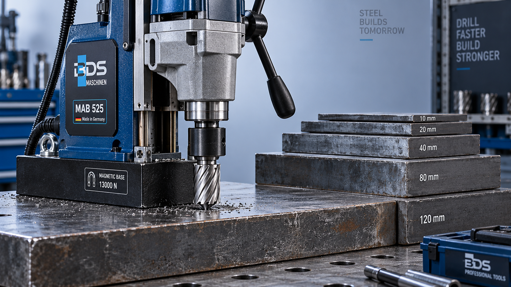
Thickness also affects mechanical stiffness. A thin sheet can flex under feed pressure or around an inadequately supported drilling location. Even with adequate magnetic attraction, a moving workpiece can destabilize the cut. Adhesion and plate support need separate checks.
What the published holding-force figure actually tells you
A catalog figure should be read alongside its test conditions. Magnetic adhesion is commonly characterized by a pull-off test, but the manufacturer’s documentation must establish the loading direction and procedure. A force measured perpendicular to a clean plate does not automatically describe resistance to sideways sliding, twisting, or peeling during drilling.
This distinction becomes particularly important on vertical steel. Machine weight acts along the surface, while drilling introduces feed reaction, cutting torque, and potentially an overturning moment. A large pull-off figure is not a direct allowable load for that combination.
Before comparing machines, request the following information:
- The steel grade, plate thickness, and surface condition used for the rating.
- The test method, force direction, and whether the figure represents maximum measured attraction or another defined value.
- The specified minimum workpiece thickness and any holding-force-versus-thickness data.
- Restrictions for coatings, curved surfaces, vertical work, and overhead operation.
- For an electromagnetic base, the supply conditions and behavior following power interruption.
Units deserve attention too. Newtons and kilonewtons express force; kilograms express mass. If a brochure lists “kg” of holding capacity, ask whether it means kilogram-force. Do not treat that number as a safe suspended load. Likewise, ask which test standard or documented internal procedure supports the rating rather than assuming all suppliers use an equivalent method.
Thickness cannot compensate for a poor contact surface
Thick steel can still provide disappointing adhesion when the magnetic base cannot make proper contact. Paint, rust scale, trapped chips, and surface irregularities introduce gaps into the magnetic circuit. Because these gaps have much higher magnetic reluctance than steel, a small separation can matter significantly.
On a fabricated beam, inspect the actual landing area rather than relying on the nominal flange thickness. Weld spatter may lift one edge of the base. A narrow flange may not support the full pole footprint. Near an edge or opening, the available flux path may differ from the broad test plate used for the catalog rating.
Steel type matters as well. Do not assume that every stainless steel is suitable: many austenitic grades provide insufficient magnetic attraction for this application. Where the material is uncertain, verify compatibility before planning the drilling method. Surface preparation must also respect coating specifications and project requirements; removing protective paint is not automatically acceptable.
Cutter selection changes the stability requirement
The magnetic base must remain stable throughout the cut, not merely while the motor is idle. Cutter diameter, sharpness, feed, material hardness, and breakthrough behavior influence the forces transmitted into the machine. Chatter or cutter grabbing can create transient loads that a static holding-force number does not describe.
Consider the listed 35mm drill bit, a tungsten-carbide-tipped annular cutter specified with a 35 mm cutting depth and 46–50 mm cutting diameters. The distinction is important: 35 mm describes depth capacity here, not hole diameter. Selecting it requires checking the drill’s approved cutter capacity, spindle interface, speed range, and workpiece setup—not just magnetic attraction.
Universal and Weldon shank options also require confirmation against the actual arbor. A cutter that physically fits is not necessarily approved for the machine or application. On thin material, annular cutting does not remove the need for an adequately supported plate and a manufacturer-approved mounting arrangement.
How to evaluate a thin-plate application
Start with the least favorable intended setup: the thinnest plate, the most restricted base position, and the largest planned cutter. Compare those conditions with the machine manual before conducting any trial. If the plate is below the specified minimum thickness, do not infer suitability from a firm-feeling magnet or an illuminated status indicator. Indicators may monitor different conditions; check what yours actually measures.
A backing plate is sometimes proposed as a remedy, but loose steel placed beneath the workpiece is not a guaranteed solution. Its effectiveness depends on contact, geometry, and the complete magnetic path. Use only a manufacturer-approved arrangement. Where adequate mounting cannot be established, mechanical clamping, a suitable fixture, or another drilling process is the better choice.
Fit the specified safety restraint to an appropriate anchorage, especially for vertical or overhead work where permitted. A chain or strap limits consequences if adhesion is lost; it does not increase the base’s holding force or make an unsuitable setup acceptable. Power-loss behavior also needs explicit review for electromagnetic machines.
For Shandong VEDON Intelligent Equipment Co., Ltd., whose business spans CNC machine tools, intelligent manufacturing solutions, and precision cutting tools, this is a system-level selection issue: machine, cutter, material, and restraint must be considered together. The useful technical discussion begins with the intended workpiece, not an isolated catalog number.
Before approving a magnetic drill, obtain the thickness conditions behind its rating and document the proposed mounting arrangement. If those conditions do not match the job, request application-specific guidance rather than applying an unsupported correction factor. A high holding-force figure is useful only when its limits are understood.

Vedon
Typically replies within minutes
Any questions related to Home?

William / CEO / Brand Founder

Elaine / Sales Manager

Jaye / Sales Director