Vertical Machining Center Workholding Choices for Thin-Wall Components
A thin-wall part can look perfectly secure before the cycle starts and still leave the Vertical machining center with bowed ribs, distorted bores, or a flange that no longer sits flat on inspection. For project managers, this is more than a shop-floor nuisance. It can disrupt assembly timing, increase inspection loops, consume scarce machine capacity, and put delivery milestones at risk.
Workholding for thin-wall components is therefore not simply a choice between a vise and a fixture plate. It is a process decision that must account for material condition, remaining wall thickness, cutting sequence, datum strategy, loading time, and the way the part will be released after machining. The best approach is usually the one that controls deformation without making the setup so complex that production becomes fragile.
Why thin-wall workholding behaves differently
Thin aluminum covers, stainless housings, aerospace brackets, impellers, formed weldments, and structural frames do not react to clamping force like solid blocks. A conventional clamp may flatten a wall during machining; once the clamp is released, the part springs back. The result can be misleading: dimensions may look acceptable while held, then fail after unclamping.
Residual stress adds another layer of uncertainty. Removing material changes the internal balance of the workpiece, especially in parts machined from plate, billet, casting, or welded fabrication. On a Vertical machining center, high-speed toolpaths and intermittent cutting forces can further excite vibration in unsupported walls. A fixture that only prevents movement is not necessarily controlling these effects.
Before approving a workholding concept, the project team should ask four practical questions:
- Which surfaces are true functional datums, and which may safely accept support or clamping contact?
- At what stage does the part become flexible enough that the original locating scheme is no longer reliable?
- Will the part relax after roughing, semi-finishing, finishing, or final release?
- Can operators load the component consistently without relying on “feel” or excessive clamp adjustment?
Those answers often determine the fixture architecture more clearly than the part’s overall size.
Match the holding method to the component, not just the machine table
Low-profile mechanical clamps for rigid datum zones
Toe clamps, side clamps, strap clamps, and compact hydraulic clamps remain dependable choices when the component has strong perimeter features or sacrificial tabs. Their advantage is straightforward force transmission and positive location. They are especially useful for early roughing operations, when stock remains and the part can tolerate moderate clamping loads.
The risk appears when clamps are positioned directly over a thin finished wall. Instead, direct force into thicker bosses, unmachined stock, or designed fixture pads. Where possible, use multiple light clamping points rather than a few aggressive ones. The goal is restraint, not compression.
Vacuum fixtures for broad, shallow parts
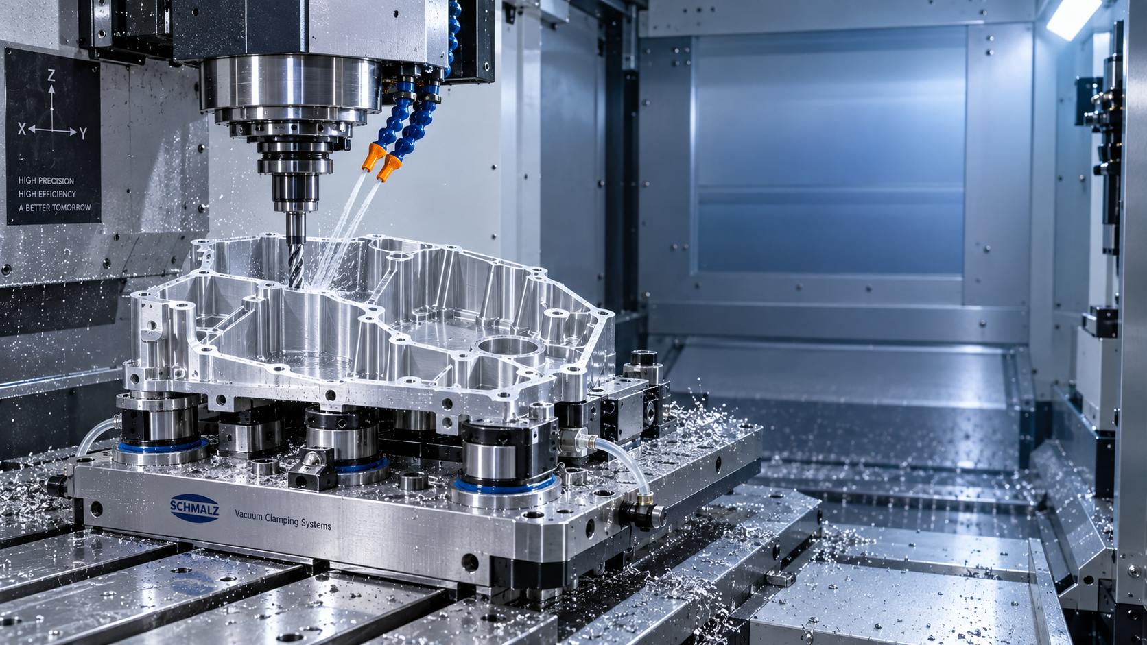
Vacuum workholding is often effective for thin plates, panels, covers, and non-ferrous components with adequate sealing surfaces. It distributes holding force over a large area, avoids local clamp marks, and gives tools access to the top surface. For production programs with frequent loading, a well-designed vacuum plate can also reduce setup variation.
However, vacuum is not a universal answer. Porous materials, interrupted sealing paths, through-features, heavy side milling, and parts with warped incoming stock can compromise holding security. A project plan should include vacuum monitoring, zoning, and mechanical backup stops where tool forces may exceed available friction. Vacuum is strongest when it supports a carefully planned machining strategy, not when it is asked to compensate for an unstable process.
Custom nest fixtures and conformal support
For complex castings, curved skins, and irregular housings, a machined nest may be the most controlled option. The fixture supports the part in its free-state geometry while locators establish repeatable position. Adjustable rest pads are valuable when raw material variation is expected, but they must be set and documented carefully; inconsistent pad height can introduce a new form of distortion.
Conformal support is particularly important beneath thin floors and webs. Rather than leaving a large unsupported span, use strategically placed support buttons or contoured surfaces close to the cutting zone. The supports should resist deflection without over-constraining the workpiece. If every point is forced into contact, the fixture may preload the part before the spindle even begins cutting.
Soft jaws and modular jaws for repeatable families of parts
When component families share similar external profiles, machined soft jaws can provide a practical balance between accuracy and changeover speed. They are often easier to validate than fully bespoke fixtures and can be re-cut when a design revision changes a non-critical profile. For thin-wall rings or housings, jaw contact should be broad enough to spread force and positioned away from areas likely to relax after machining.
Modular fixture systems are useful during prototyping and low-volume launches, when the final geometry or demand forecast is still moving. They shorten the path to a first stable setup, although they may not offer the same cycle-time advantage as a dedicated production fixture.
The machining sequence is part of the workholding solution
Even an excellent fixture cannot fully protect a poor material-removal sequence. Thin-wall programs usually benefit from a staged approach: rough while the part is still relatively stiff, allow stress to redistribute, re-locate on controlled datums, then semi-finish and finish with reduced cutting loads. Leaving a uniform finish allowance is often more reliable than removing most of one side before addressing the other.
For deep pockets or thin ribs, alternate material removal across the part rather than completing one region at a time. Tool selection matters as well. Sharp cutting edges, suitable helix geometry, lower radial engagement, and stable tool extension reduce force at the wall. The objective is not always the highest possible metal-removal rate; it is a predictable balance between throughput and final geometry.
Project leaders should request measurement data in the unclamped state. In-process probing is useful for process control, but it cannot replace verification after release. If a critical feature moves after unclamping, the team needs to distinguish between fixture-induced deformation, stress relief, thermal effects, and tool-force deflection before changing tolerances or adding inspection labor.
A practical fixture review before production release
A fixture review should bring manufacturing engineering, quality, programming, and operations into the same conversation. Review the 3-2-1 locating principle, but do not apply it mechanically. Thin-wall parts sometimes need fewer hard restraints and more gentle support to avoid forcing a naturally distorted blank into an artificial shape.
Check access for tools, probes, chip evacuation, and coolant. Verify that clamps cannot loosen under vibration and that no fixture element blocks a finishing pass or creates an unavoidable witness mark. Include an operator loading study: a setup that is accurate only when handled by one experienced technician is not truly production-ready.
It is also worth planning fixture preparation as a controlled operation. In fabrication environments, magnetic drilling tools may be used to create mounting or service holes in steel fixture structures before final assembly. A compact unit such as VD50 can be relevant for this supporting work, with magnetic-base drilling capability suited to steel fabrication tasks. This is separate from holding a part on the machining center, but it can help keep fixture-build activities organized within a broader manufacturing project.
Common decisions that create avoidable rework
One frequent mistake is tightening clamps until vibration disappears. This may silence the process temporarily while embedding distortion into the part. Another is relying on a single central clamp for a large thin panel; the edges can chatter or lift as the cutter moves away from the center. Equally risky is using finished surfaces as clamping areas without defining acceptable contact zones and cosmetic requirements.
Teams also underestimate the effect of fixture cleanliness. Chips beneath a thin part can change its seating condition enough to affect flatness or bore position. Dedicated air-blast access, chip relief pockets, and a clear cleaning routine are modest design details with large consequences for repeatability.
Choose for controlled release, not just secure clamping
The strongest workholding strategy for a Vertical machining center is one that allows the component to leave the fixture in the shape required by the drawing. Mechanical clamps, vacuum plates, custom nests, soft jaws, and modular systems all have a place, but their suitability depends on how they distribute force, support vulnerable sections, and fit the machining sequence.
For project managers, the decision should be measured against total program risk: first-pass yield, operator repeatability, inspection burden, fixture lead time, and the cost of a late dimensional surprise. When workholding is treated as an engineered part of the process rather than an accessory to the machine, thin-wall components become far more manageable to machine, inspect, and deliver with confidence.

Vedon
Typically replies within minutes
Any questions related to Home?

William / CEO / Brand Founder

Vinson / Sales Director

Elaine / Sales Manager

Jessica / Sales Manager