Key Universal Milling Machine Parameters That Affect Machining Accuracy
Key Universal Milling Machine Parameters That Affect Machining Accuracy
For quality control and safety teams, machining accuracy depends on controlling a connected system rather than monitoring one setting in isolation.
On a Universal milling machine, spindle behavior, feed, tooling, fixturing, alignment, rigidity, and temperature directly influence dimensional conformity, surface finish, repeatability, and operator safety.
Start With a Control Plan for Critical Accuracy Risks
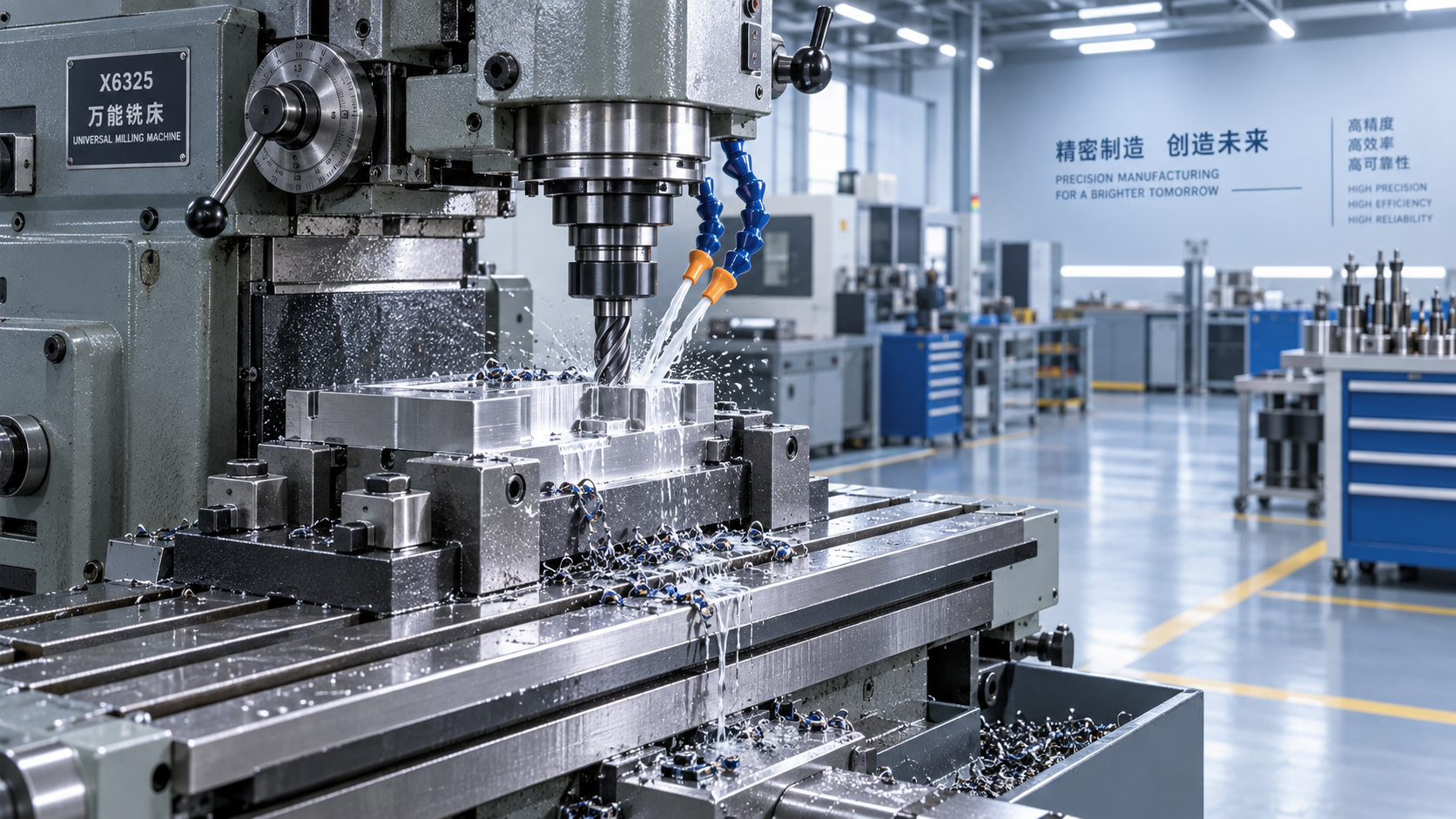
Quality teams should first identify the critical product characteristics: hole position, flatness, perpendicularity, surface roughness, profile accuracy, and dimensional tolerances specified by the drawing.
Each characteristic should be linked to machine parameters, inspection methods, acceptable limits, sampling frequency, and escalation actions when process capability begins to decline.
This approach prevents a common mistake: inspecting finished parts thoroughly while overlooking the operating conditions that create variation during milling.
Safety personnel should also include guarding status, emergency-stop function, chip control, coolant handling, fixture security, and abnormal vibration within routine machine checks.
A stable process produces more than accurate parts. It reduces rework, unexpected tool failure, flying-chip exposure, fixture movement, and the pressure to make unsafe production adjustments.
Spindle Speed and Feed Rate Must Work Together
Spindle speed determines cutting speed at the tool edge, while feed rate determines how aggressively the cutter advances through the workpiece material.
When spindle speed is too high, heat can rise quickly, accelerating wear and causing thermal growth, burning marks, poor finish, or edge deterioration.
When speed is too low, the cutter may rub instead of cut efficiently, increasing cutting force, vibration, built-up edge, and inconsistent dimensions.
Feed rate deserves equal attention because excessive feed can overload the tool, deflect the workpiece, and create chatter marks or oversized features.
Insufficient feed can also be harmful. It may produce rubbing, excessive heat, poor chip formation, and shortened tool life despite seemingly gentle cutting conditions.
For a Universal milling machine, the correct speed and feed combination should be established by material, cutter diameter, tool coating, engagement depth, coolant strategy, and required finish.
Quality staff should compare actual machine settings with approved process sheets, especially after setup changes, program revisions, tooling substitutions, or operator handovers.
Recording actual values matters because nominal settings alone cannot reveal overrides, manual adjustments, unstable spindle output, or feed reductions made to compensate for problems.
Tool Condition Is a Leading Indicator of Dimensional Drift
A dull, chipped, incorrectly installed, or poorly balanced cutter changes cutting forces before inspection data necessarily shows a clear dimensional failure.
Tool wear commonly causes burr formation, declining surface finish, increased noise, heat discoloration, and gradual movement toward tolerance limits on repeated production runs.
Quality control plans should define measurable replacement triggers, such as part count, wear-land limit, spindle-load trend, roughness change, or dimensional trend.
Visual tool checks are useful, but they should not replace controlled tool-life management for features with tight positional or geometric tolerance requirements.
Tool runout is especially important. Excessive runout makes one flute cut more heavily, leading to uneven wear, inaccurate diameters, poor finish, and vibration.
Measure runout at the toolholder and near the cutting edge when practical. Clean tapers, undamaged collets, and correct tightening torque support repeatable results.
Safety teams should treat damaged cutters and improvised toolholding as immediate risks because breakage can release sharp fragments at high rotational speed.
Machine Rigidity, Fixturing, and Alignment Determine Repeatability
Even correct cutting parameters cannot compensate for a flexible machine, loose fixture, unsupported workpiece, worn slideway, or poorly aligned spindle and table.
Rigidity determines how well the machine resists cutting forces without deflection. Deflection can create taper, inaccurate slots, poor perpendicularity, and inconsistent feature positions.
Fixtures should locate the part from controlled datums, clamp without distortion, provide sufficient support, and keep cutting forces directed into stable restraint points.
Operators should never compensate for weak clamping by reducing feed blindly. The resulting process may still shift parts while masking the underlying safety and quality problem.
Routine checks should include vise condition, clamp wear, fixture fasteners, table cleanliness, backlash, gibs, spindle bearings, and machine-level verification.
Alignment verification is particularly important after relocation, collision, heavy interrupted cuts, maintenance activity, or complaints involving squareness, parallelism, or positional accuracy.
Use calibrated indicators, test bars, precision squares, and documented acceptance criteria instead of relying only on operator judgment or prior machine performance.
Thermal Stability and Coolant Control Affect Long Runs
Thermal variation is often underestimated because a machine may produce acceptable first-off parts but drift as the spindle, tool, fixture, and workpiece warm.
Long production cycles require warm-up procedures, consistent ambient conditions where possible, stable coolant delivery, and inspection schedules that detect gradual dimensional movement.
Coolant concentration, flow direction, and cleanliness influence heat removal, tool life, corrosion control, chip evacuation, and the reliability of in-process measurement.
Insufficient coolant flow can leave chips in a pocket or slot, causing recutting, surface damage, heat buildup, and sudden tool overload during subsequent passes.
Safety managers should confirm that coolant systems do not create slip hazards, mist exposure, blocked drains, or unsafe cleaning practices around rotating equipment.
For high-accuracy work, compare cold-start, mid-run, and late-run measurements. This reveals whether process variation is linked to temperature rather than random inspection error.
Where thermal drift is significant, adjust process controls before changing tolerances. Better warm-up, cooling, sequencing, and compensation are usually more defensible solutions.
Verify the Measurement System Before Blaming the Machine
An apparent milling problem may actually be caused by an unsuitable gauge, inconsistent measurement technique, contaminated reference surface, or uncontrolled inspection environment.
Measurement system analysis should confirm that gauges have adequate resolution and that repeatability and reproducibility are appropriate for the specified tolerance range.
Inspectors should measure from the same datums used during machining whenever possible. Different reference schemes can create misleading conclusions about machine accuracy.
Trend charts are more useful than isolated measurements. A steady directional shift may indicate wear, heat, backlash, or fixture movement before out-of-tolerance parts appear.
When a trend is detected, contain affected production, verify the measurement system, inspect tooling and fixturing, then review actual parameter history before restarting.
This sequence protects customers while avoiding unnecessary adjustments that introduce new variation into a process that may not be the true source of error.
Connect Milling Accuracy Controls With Related Fabrication Work
Many fabrication teams use milling alongside drilling, reaming, tapping, and installation work, where accurate hole preparation affects final assembly quality and structural safety.
For portable drilling tasks on steel structures, equipment selection should consider holding force, positioning accuracy, stroke, power, drilling range, and operator handling requirements.
The VDD80Z magnetic drilling solution supports core drilling, twist drilling, tapping, reaming, half-hole drilling, and beveled hole drilling for demanding fabrication environments.
Its high magnetic holding capability and compact portable design can support controlled holemaking in applications including bridges, shipbuilding, railways, power plants, pipelines, and machinery manufacturing.
However, portable equipment still requires surface preparation, secure magnetic contact, correct cutter selection, controlled feed, chip management, and pre-use safety inspection.
Quality and safety teams should apply the same discipline used on a Universal milling machine: control the setup, verify the parameters, inspect critical outputs, and investigate trends early.
Build a Practical Daily Accuracy Checklist
A daily checklist should confirm spindle condition, lubrication, guards, emergency stops, coolant flow, table cleanliness, toolholder condition, fixture security, and abnormal machine noise.
Before production, verify the approved program or setup sheet, tool offsets, spindle speed, feed rate, work offset, cutter identity, and inspection gauge availability.
During production, monitor first-off results, tool wear, chip shape, vibration, spindle load, surface finish, and dimensional trends at planned intervals.
After a collision, tool breakage, power interruption, fixture movement, or unexpected alarm, require documented re-verification before parts return to normal production flow.
Clear ownership is essential. Operators monitor conditions, inspectors verify outputs, maintenance restores equipment capability, and safety personnel address risks before they become incidents.
Conclusion
Machining accuracy on a Universal milling machine is the result of controlled parameters, stable equipment, capable tooling, secure fixturing, reliable measurement, and disciplined operating practices.
For quality control and safety teams, the strongest strategy is to monitor leading indicators, document trends, and correct root causes before defects or hazardous conditions escalate.
When spindle speed, feed, tool condition, alignment, thermal behavior, and inspection systems are managed together, production becomes more predictable, safer, and easier to improve.

Vedon
Typically replies within minutes
Any questions related to Home?

William / CEO / Brand Founder

Elaine / Sales Manager

Jessica / Sales Manager