


Preventing Thermal Drift in Vertical Machining Center Precision Parts
Thermal drift is rarely a sudden machine failure. It is a gradual movement of the spindle, structure, ballscrews, workpiece, or measuring reference as temperatures change. The danger is that a Vertical machining center may produce acceptable first-off parts, then move out of tolerance after the spindle reaches operating temperature or after several hours of continuous cutting. By the time the deviation appears in final inspection, a substantial batch may already require sorting, rework, or rejection.
For precision parts, the practical issue is not whether heat exists—it always does—but whether the thermal condition at machining, probing, and inspection is controlled well enough for the tolerance being held. A process that is stable at a 30 μm tolerance can become unreliable when critical positional, bore-size, flatness, or profile requirements fall into the low-micron range.
Identify where the displacement is coming from
Thermal drift is often treated as a spindle problem, but its sources are distributed across the machining system. A changing spindle centerline affects tool length, bore position, and circular features. Ballscrew heating can shift an axis position, especially over long travel distances. Servo motors, guideway friction, hydraulic units, coolant temperature, and uneven heat from chips accumulating around the workpiece can all alter the relative position between tool and part.
The workpiece itself may be the dominant source. A large steel, aluminum, or cast component can expand during aggressive roughing, particularly when material is removed asymmetrically. If a finishing feature is machined while the part is warm and then inspected after cooling, the result may appear as a dimensional error even if the machine followed the programmed coordinates correctly.
Ambient changes matter as well. Direct morning sunlight, a roller door left open during loading, cold air from a ventilation outlet, or a shift change in coolant use can produce local temperature gradients. These conditions do not always cause a large average temperature change in the workshop, but they can heat one side of a machine column, table, fixture, or inspection gauge enough to influence precision work.
The useful quality question is therefore: which physical relationship is moving? Distinguishing among spindle-to-table movement, axis positioning change, fixture movement, workpiece growth, and metrology variation prevents ineffective corrective actions.
Do not qualify a process only in its cold state
A cold-machine capability check can give false confidence. If production involves high spindle speed, sustained roughing, long axis strokes, frequent tool changes, or extended unmanned cycles, qualification needs to reflect that duty cycle. A machine may repeat accurately once thermally stabilized yet produce a predictable offset during its warm-up phase.
A practical control plan begins by recording critical feature results against machine operating time. The record should include machine start time, spindle running time, spindle speed range, cutting load, coolant state, ambient condition where relevant, tool number, and fixture identity. The goal is not to create paperwork for every dimension; it is to identify whether a specific critical feature trends in one direction as thermal input rises.
For example, if a bore center shifts consistently after 45 minutes of high-speed operation, the response may be a defined warm-up cycle, a scheduled in-process offset verification, or thermal compensation validated under the actual cutting pattern. If the feature changes only after a large roughing operation, the process review should focus more closely on part temperature, stock-removal sequence, clamping, and the timing of finishing passes.
First-piece inspection remains necessary, but it should be paired with checks at the point where the machine and workpiece reach their normal production thermal state. A process is not fully controlled merely because the first part conforms.
Build warm-up routines around thermal behavior, not elapsed time alone
A warm-up cycle should bring the machine into a repeatable condition before high-precision work begins. Simply leaving the control powered on does not stabilize the spindle, feed axes, or coolant system. The routine should include controlled spindle operation across the speed range expected for the job and representative axis movement. The required duration depends on machine design, spindle type, cutting program, and the tolerance of the finished part, so a generic time setting should not be adopted without verification.
Warm-up also needs to be repeated after conditions that materially change the machine state: a long idle period, a major spindle-speed change, maintenance affecting alignment or lubrication, extended door-open setup, or a significant interruption in coolant circulation. The relevant trigger is not the calendar; it is a change in the heat balance that the qualified process assumes.
On machines with thermal compensation functions, compensation should be regarded as a controlled process parameter, not an automatic guarantee. Its effectiveness depends on correct sensor behavior, stable machine geometry, suitable compensation logic, and an operating condition close to that used for validation. Compensation cannot reliably correct a loose toolholder interface, an unstable fixture, excessive spindle bearing heat, or uneven workpiece heating.
Control the process heat introduced by cutting
Reducing heat is not always the right objective. In some applications, consistent heat generation is more valuable than lower but variable heat generation. A stable roughing strategy, repeatable coolant delivery, and predictable finishing allowance create a condition that can be measured and controlled.
Several process details have disproportionate effect on thermal consistency:
- Tool condition: A worn cutting edge raises cutting force and heat. Tool-life limits should be based on feature stability and surface integrity, not only on whether the tool can still remove material.
- Coolant concentration and flow: Inconsistent concentration, blocked nozzles, poor aim, or intermittent flow changes both cutting temperature and chip evacuation. The resulting variation can alter size and leave chips that interfere with seating surfaces.
- Machining sequence: Heavy stock removal close to a critical finishing feature can locally heat the part or release residual stress. A finishing pass performed after thermal recovery may be more stable than one performed immediately after aggressive roughing.
- Fixture contact: Locating faces must remain clean and accessible to coolant and chip control. A fixture heated by repeated cutting cycles can move the workpiece reference even when clamp force remains unchanged.
Thin-walled parts require special caution. Their geometry changes under clamping force, cutting load, and temperature more readily than rigid components. For these parts, a finished dimension measured while clamped may not represent the free-state dimension after cooling. The inspection method must reflect the drawing requirement: restrained condition, free condition, or a specified measurement sequence.
Use probing and inspection without creating a false reference
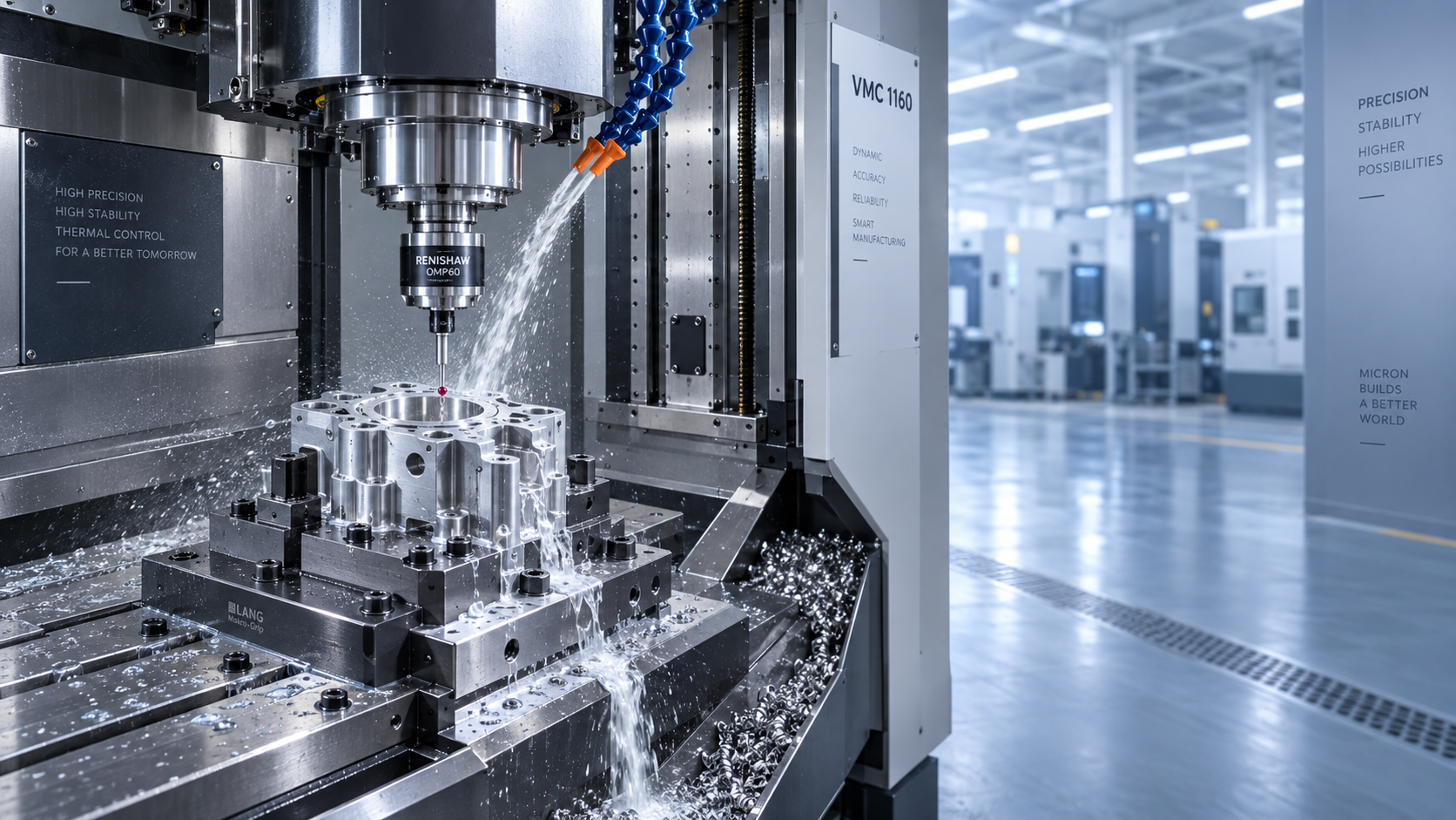
On-machine probing can detect drift before parts leave the machine, but it measures the relationship between the probe, machine coordinates, and the workpiece at that moment. It does not automatically establish the final cooled-state dimension. A probe strategy is most valuable when its datum surfaces are clean, thermally representative, and measured at a defined point in the cycle.
Probe calibration must also be protected from thermal instability. Calibrating a probe on a reference sphere when the spindle and machine are cold, then relying on it after a long high-speed cycle, can embed thermal movement into the measurement result. The calibration interval should be linked to the risk profile of the job and the stability demonstrated by process data.
Final inspection has similar limitations. Gauge blocks, CMM fixtures, bore gauges, and the component should be allowed to reach compatible measurement conditions when tolerances require it. A part transferred directly from a warm machine to a temperature-controlled inspection area may show a changing result during stabilization. Recording part temperature or applying a documented measurement procedure can be more meaningful than repeatedly remeasuring an unstable part and averaging the readings.
Machine condition sets the limit of procedural control
Process discipline cannot compensate indefinitely for a machine with a developing mechanical or thermal fault. A new drift pattern, a larger warm-up requirement, unusual spindle noise, rising vibration, erratic axis following error, recurring tool-length variation, or a change in coolant temperature behavior should trigger maintenance review before offsets are repeatedly adjusted.
Machine architecture and capacity influence how much thermal variation a process must manage. For example, a large-travel machine used for heavy workpieces needs adequate structural stability, axis-drive consistency, and fixture support across its working envelope. The VMC1370 has 1300 mm X-axis travel, a 700 mm Y-axis travel, a 1200 kg table load rating, and a one-piece cast bed. These specifications may support demanding part sizes, but they do not replace acceptance testing under the buyer’s own cutting cycle, tool lengths, fixture mass, and critical tolerance locations.
Published positioning and repeatability values should likewise be interpreted carefully. They describe machine capability under stated test conditions, whereas production accuracy is affected by thermal state, tool system quality, setup practice, program path, load, and inspection method. The important acceptance question is whether the machine can maintain the required feature tolerance after it reaches the thermal condition expected in production.
Set reaction limits before nonconforming parts accumulate
A useful thermal-drift control plan defines what happens when a monitored feature begins to move. The response may include pausing the cycle, checking tool wear and retention, confirming coolant flow, removing chips from datum areas, verifying probe calibration, running a stabilization cycle, or segregating parts made since the last confirmed check. The action should be based on the nature of the movement, not an assumption that every deviation is a programming error.
Trend data is more informative than isolated measurements. A gradual, repeatable shift may be managed through a qualified thermal routine or controlled offset strategy. A sudden, irregular shift is more likely to indicate an unstable tool, fixture, coolant condition, axis issue, or measurement problem and should not be normalized through routine offset changes.
Thermal stability is achieved when the machine, tooling, workpiece, coolant, and inspection system are treated as one measurement chain. That approach reduces the risk of passing parts only under temporary conditions and makes precision machining more predictable across long production cycles.

Vedon
Typically replies within minutes
Any questions related to Home?

Elaine / Sales Director

Jessica / Sales Manager

Jaye / Sales Manager