Reducing Setup Errors When Machining Angled Features on Universal Mills
Machining an angled face, slot, shoulder, or drilled pattern on a Universal milling machine often looks straightforward on the route sheet. In practice, it is one of the operations most likely to create costly disagreement between the drawing, the first-off inspection report, and the part on the table. A small setup error can shift an angle, move a feature from its true position, reduce remaining wall thickness, or cause a cutter to enter material in an unsafe condition.
For quality and safety managers, the concern is not simply whether an experienced operator can produce one acceptable part. The real question is whether the setup can be repeated, verified, released, and monitored without relying on individual judgment alone. Disciplined angular setup control reduces scrap, protects tooling and fixtures, and gives inspectors a defensible basis for accepting production.
Why angled work creates more risk than a standard milling setup
A flat workpiece placed squarely in a vise has a relatively simple datum chain: the vise is aligned to the machine axis, the part rests on known surfaces, and the cutting path follows a programmed or hand-fed coordinate direction. Angled machining adds another relationship to control. The workpiece, fixture, table, spindle head, or cutter must be rotated by a known amount—and that rotation has to be referenced to the correct drawing datum.
This is where seemingly minor assumptions create defects. A machinist may set the swivel table to the print angle but reference a rough edge rather than the specified datum face. A sine bar may be calculated correctly but rest on a burred surface. A tilting fixture may be secure at rest but settle slightly once cutting forces increase. Each condition can produce a part that looks plausible while failing functional assembly.
There is also a safety dimension. When an angled setup raises one side of a part, it may reduce clamping contact, increase leverage on the vise jaws, or bring the tool closer to clamps and fixture hardware. On a universal mill, a setup that is dimensionally uncertain is often mechanically uncertain as well.
Begin with the datum chain, not the angle setting
The angle value on a drawing should never be treated as the entire setup instruction. Before a workpiece reaches the table, review what the angle is measured from, which surfaces establish the part coordinate system, and whether the tolerance applies to profile, angularity, orientation, or feature location. These controls are not interchangeable.
A useful pre-setup discussion between production and quality should answer four questions:
- Which surface or axis is the primary datum for the angled feature?
- Will the feature be created by rotating the part, rotating the table, or using an angular cutter path?
- What inspection method will confirm the angle and its location after machining?
- Which setup surfaces must be cleaned, deburred, or machined before they can be trusted?
That last point deserves particular attention. An accurate angle plate cannot correct a casting scale patch, a chip beneath a parallel, or a distorted locating face. Quality control begins with contact integrity: clean table, clean fixture base, clean locating surfaces, and no hidden interference at the clamping points.
Choose the angular method to match the tolerance and the part
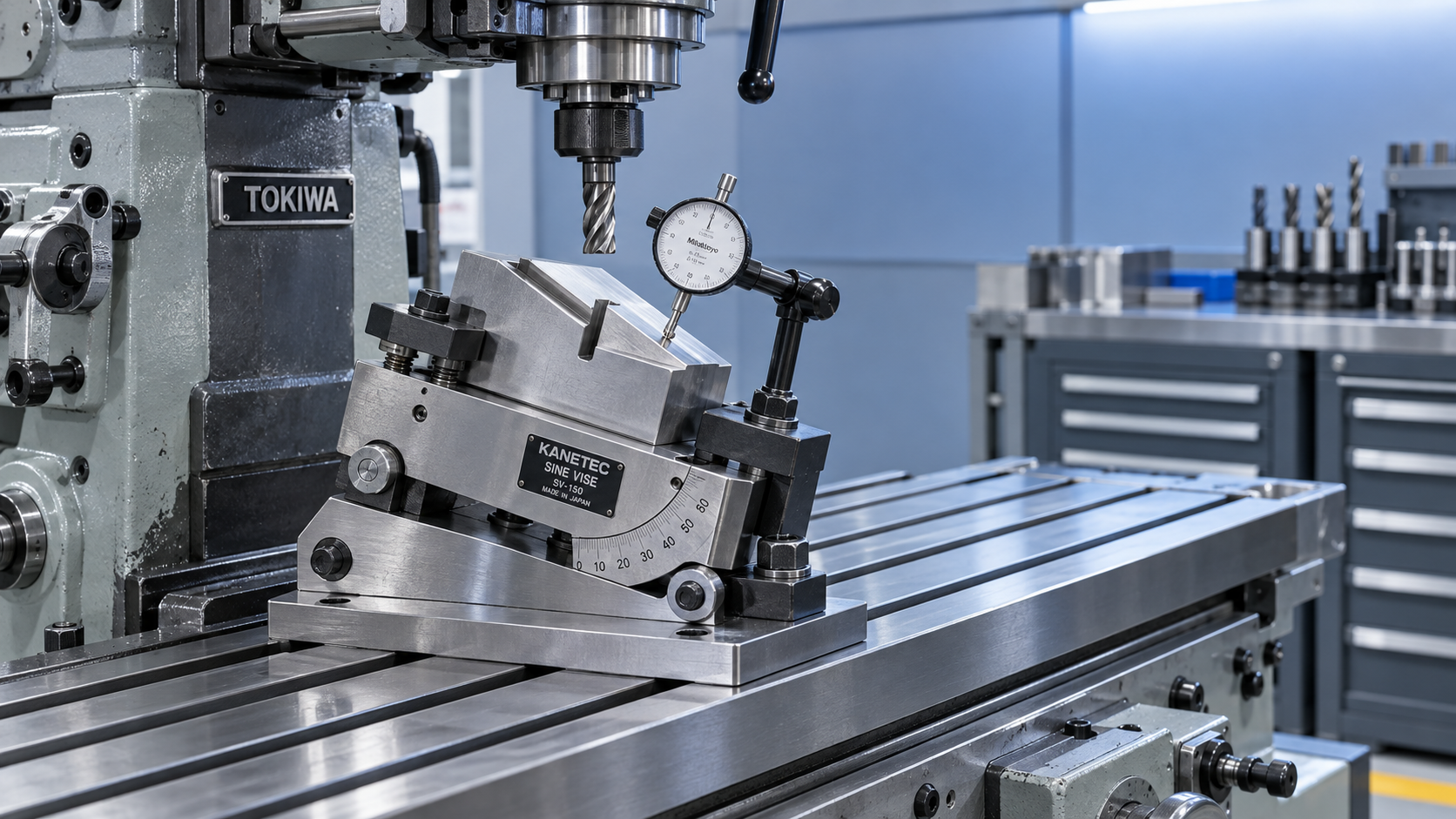
Universal mills offer several ways to generate an angle, but they do not provide the same repeatability. A swivel vise can be practical for secondary work and modest tolerances, especially when the workpiece has a broad, stable clamping surface. For more demanding angular relationships, a sine bar or sine plate with certified gauge blocks gives a more traceable basis for setup. A dedicated fixture is often justified when the same feature is produced repeatedly or when part geometry makes a vise setup vulnerable to movement.
Rotating the universal table may be suitable for long cuts or features aligned with the table travel. However, managers should confirm that the table scale is being used only within its realistic capability. Graduations are useful for rough positioning; they should not automatically be accepted as final evidence for a tightly controlled angle. A dial indicator sweep, sine setup verification, or calibrated digital angle instrument may be needed before release.
For compound-angle work, avoid treating each adjustment as independent. Tilting one plane can change how another reference surface presents to the indicator. Establish a written adjustment order, confirm the primary orientation first, then the secondary, and recheck the first after locking the second.
A verification routine that catches errors before the first cut
The strongest control point is before the cutter touches the part. A concise setup-verification sheet can make this step consistent across shifts without turning it into paperwork for its own sake. The sheet should identify the drawing revision, fixture ID, datum surfaces, required angle, measuring equipment, and the person authorized to release the first-off part.
In many operations, the following sequence is more reliable than a single “angle checked” entry:
- Confirm machine condition. Check table travel, locking function, backlash awareness, guards, coolant direction, and clearance through the complete planned tool path.
- Qualify the fixture position. Indicate the fixed reference face or keyway rather than assuming the fixture is aligned because it was used previously.
- Seat and clamp the workpiece. Apply clamping force gradually and verify that the part has not lifted, rotated, or bridged on chips.
- Verify the angle independently. Use the method specified in the control plan: indicator sweep, sine calculation, angle block, digital inclinometer, or a combination suited to the tolerance.
- Perform a dry run. Move through the approach, cut, retract, and indexing positions at safe speed. Look for clamp conflicts, insufficient clearance, and cable or coolant hose hazards.
- Machine and inspect a controlled first-off. Measure both the angle and the feature’s relationship to critical datums. A correct angle in the wrong location is still a setup failure.
The independence of the verification matters. If the same unverified table scale is used to set and “check” the angle, the process has not been truly confirmed. Quality managers should encourage a check that relies on a different reference or instrument whenever the risk level warrants it.
Clamping stability is an inspection issue as well as a safety issue
When a part is held at an angle, cutting loads do not act straight down into the vise or fixture. They can introduce sliding, lifting, or rotational forces. This is especially important during heavy roughing, interrupted cuts, and aggressive side milling. A part that shifts by a small amount may not visibly escape the fixture, yet it can invalidate the entire angular relationship.
Use positive location wherever possible: stops, hardened locators, step blocks, keys, or dedicated nests that resist force in the expected cutting direction. Clamps should press the part into its locators rather than pull it away from them. If packing is necessary, use rigid, controlled supports—not improvised stacks that can compress, tilt, or migrate under vibration.
Safety personnel should also look beyond the fixture itself. High setups can move the operator closer to rotating tooling during verification. Long-handled indicators, safe spindle-stop procedures, chip-control practices, and a clear rule against reaching into the machine before motion has stopped all support safer inspection behavior.
Common sources of false confidence
Some of the most persistent setup errors arise from checks that appear reasonable but do not prove the required condition. Reading a swivel vise scale without indicating the vise base is one example. Another is checking an angled surface after machining without confirming whether the part moved during the cut. Measuring only at one end of a long feature can miss twist, while measuring an angle without referencing the specified datum can hide a positional error.
Tool condition can also mislead the investigation. A worn end mill may deflect and leave an apparently incorrect angle even though the fixture was correctly set. Conversely, a sharp tool can temporarily mask poor clamping until a later batch or a different material exposes the weakness. Record tool type, cutter extension, feed direction, and roughing versus finishing passes when analyzing recurring variation.
Build traceability into repeat production
For recurring parts, preserve the information that made the successful setup work. Photographs of clamp positions, documented gauge-block stacks, fixture orientation sketches, approved probing routines, and first-off records can prevent the “tribal knowledge” problem that appears when a skilled operator is absent.
This approach also connects milling quality to the broader machine shop workflow. For example, a rigid turning platform such as the CW6260 may be used upstream to prepare stable cylindrical stock, shoulders, or locating diameters before an angled milling operation. Its heavy-duty machining capability, 24–1600 rpm spindle-speed range, and ISO-C8 or ISO-D8 spindle options can support controlled pre-machining of components that later require accurate secondary positioning. The milling setup should still establish its own datums, but more consistent incoming geometry reduces avoidable variation.
Shandong VEDON Intelligent Equipment Co., Ltd. approaches machine-tool selection and intelligent manufacturing support with the same practical objective: make quality repeatable rather than dependent on last-minute correction. For quality teams, that means linking equipment capability, fixture design, inspection method, and operator instructions into one usable process.
Release the process, not just the part
An acceptable first-off component is important, but it should not end the investigation. Ask whether the setup can remain stable through tool changes, operator handovers, material-lot variation, and normal machine vibration. Define when in-process checks are required: after roughing, after a set number of parts, following a cutter change, or whenever clamps are disturbed.
The most reliable angled machining on a Universal milling machine comes from making the setup visible and verifiable. When datums are explicit, fixturing resists real cutting forces, measurement is independent, and dry-run safety checks are routine, angular features become far less dependent on luck. The result is not only fewer rejected parts, but a calmer, safer production floor where operators and inspectors can trust the process they are asked to control.

Vedon
Typically replies within minutes
Any questions related to Home?

William / CEO / Brand Founder

Elaine / Sales Manager

Jessica / Sales Manager